![[LIFT] architects](/storage/layout/Header_025.png)
Entries by AOP (74)
Slow Food Nation Install Day 1
 AOP
AOP
Installation Day #1 for the Pickles Pavilion for the Slow Food Nation event in San Francisco, CA.


Suspended Ceiling using Grasshopper and Rhinoscript
 4 Comments
I finally finished the script for the exhibition space we have designed where we suspend 3024 mason jar lids from a T-bar ceiling. In order to streamline the process, I used the Grasshopper plug-in to parametrically control several aspects of the design. Below, I try to explain each step of the process and how the script works. This script is much more detailed than the previous version, as now all of the steps are embedded into 2 scripts: one grasshopper definition which deals with all of the math behind the project, and one rhinoscript that deals with exporting the data to Microsoft Excel for easy access.
The files you will need to create the suspended ceiling are as follows:
New Update: I have modified the source files to be consistent with the release of the Grasshopper plugin on 10.10.2008. You can download all of the source files for the suspended ceiling here.
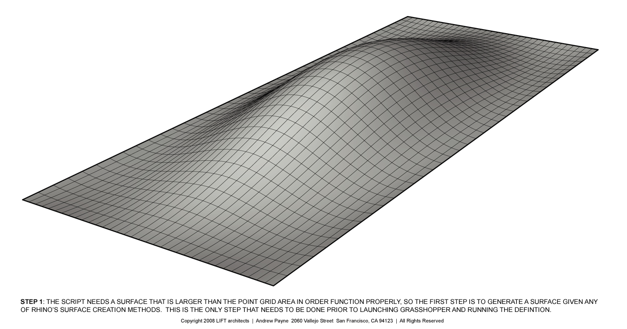 Step 1: The script needs a surface that is larger than the point grid area in order to function properly, so the first step is to generate a sufrace using any of Rhino's surface creation methods. This is the only step that is required prior to launching Grasshopper and running the definition. Click image for more detail.
 Step 2: The first part of the definition creates a staggered point grid based on a variable offset distance (inches) which is parametrically driven by an integer slider labeled "point spacing". It is important that the point grid is created above the surface (z-axis). Click image for more detail.
 Step 3: The next part of the definition duplicates the staggered point grid created in Step 2 and moves them along the z-axis so that the copies are below the given surface. Next, a vertical line is created between the original point grid and the duplicates. Click image for more detail.
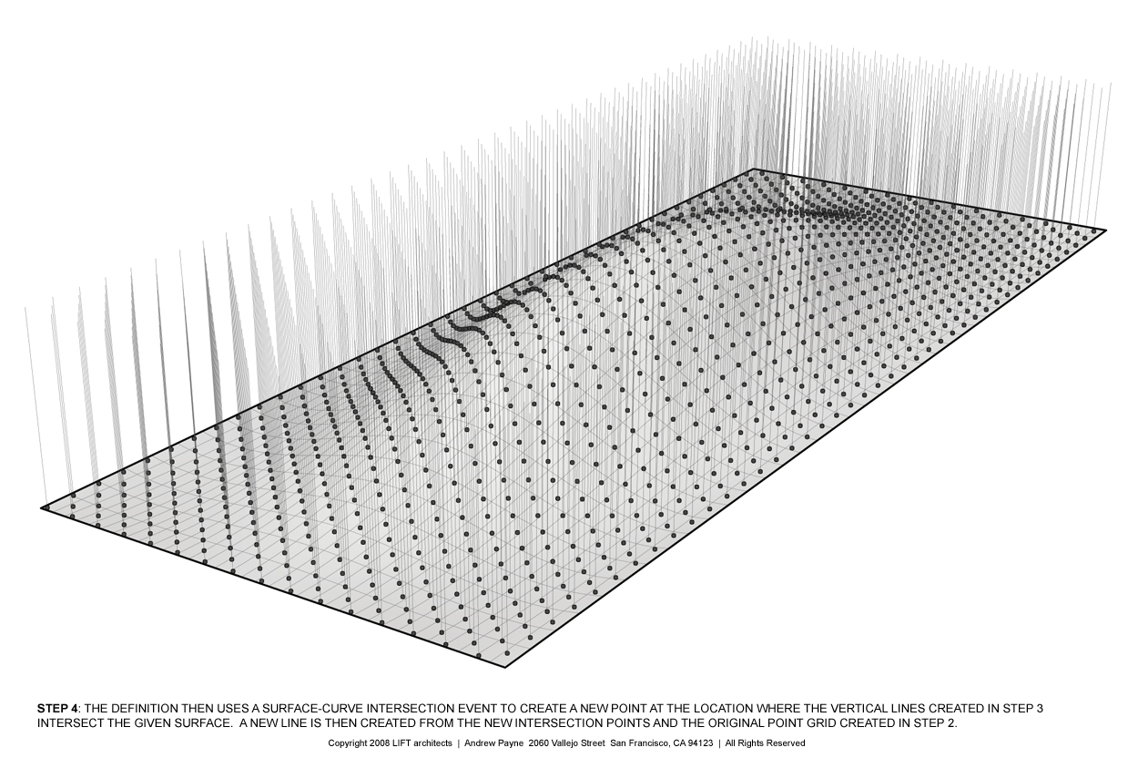 Step 4: The definition uses a surface-curve intersection event to create a new point at the location where the vertical lines created in Step 3 intersect the surface. A new line is then created from the new intersection points and the original point grid created in Step 2. Click image for more detail.
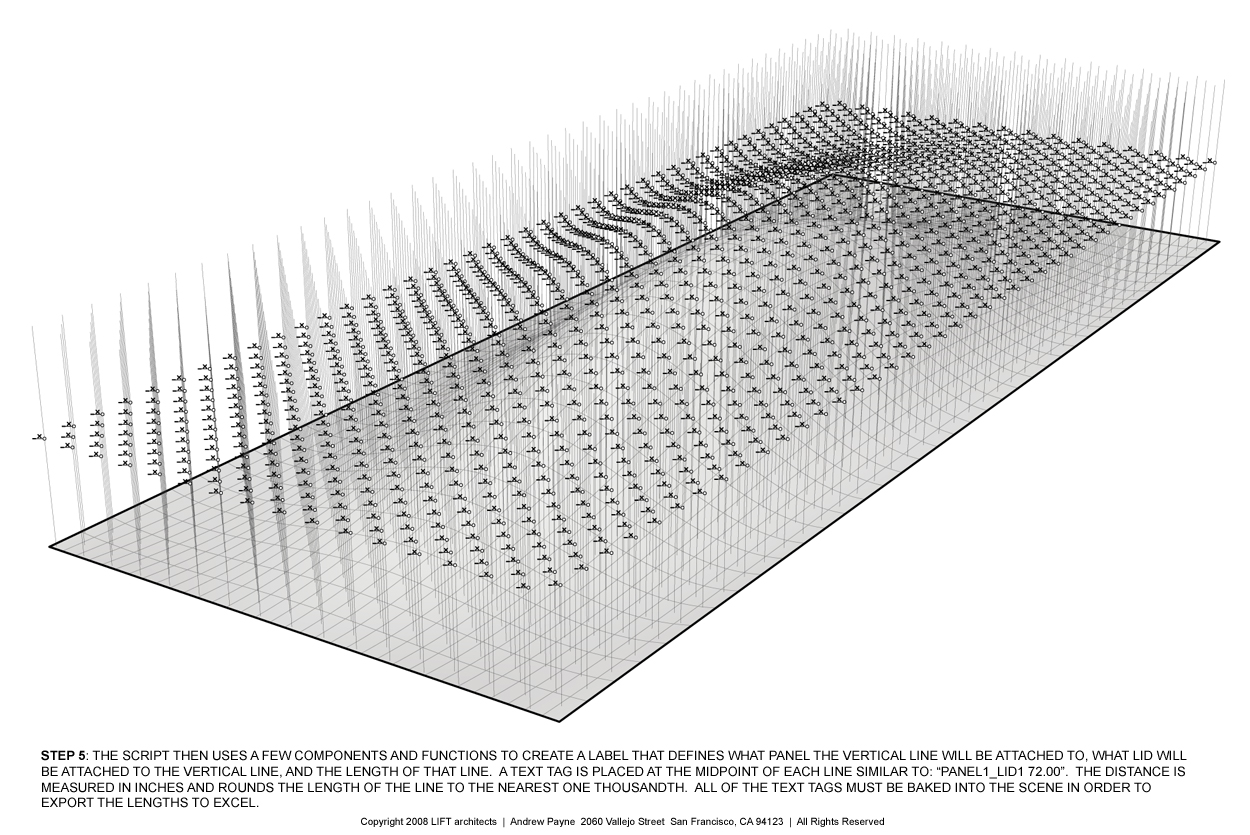 Step 5: The script then uses a few components and functions to create a label that defines what panel the vertical line will be attached to, what lid will be attached to the vertical line, and the length of each line. A text tag is placed at the midpoint of each line similar to: "Panel1_Lid1 72.000". The distance is measured in inches and rounds the length of the line to the nearest one thousandth. All text tags must be baked into the scene in order to export the data to excel. (special thanks to Troy Zezula for collaborating on this part of the script). Click image for more detail.
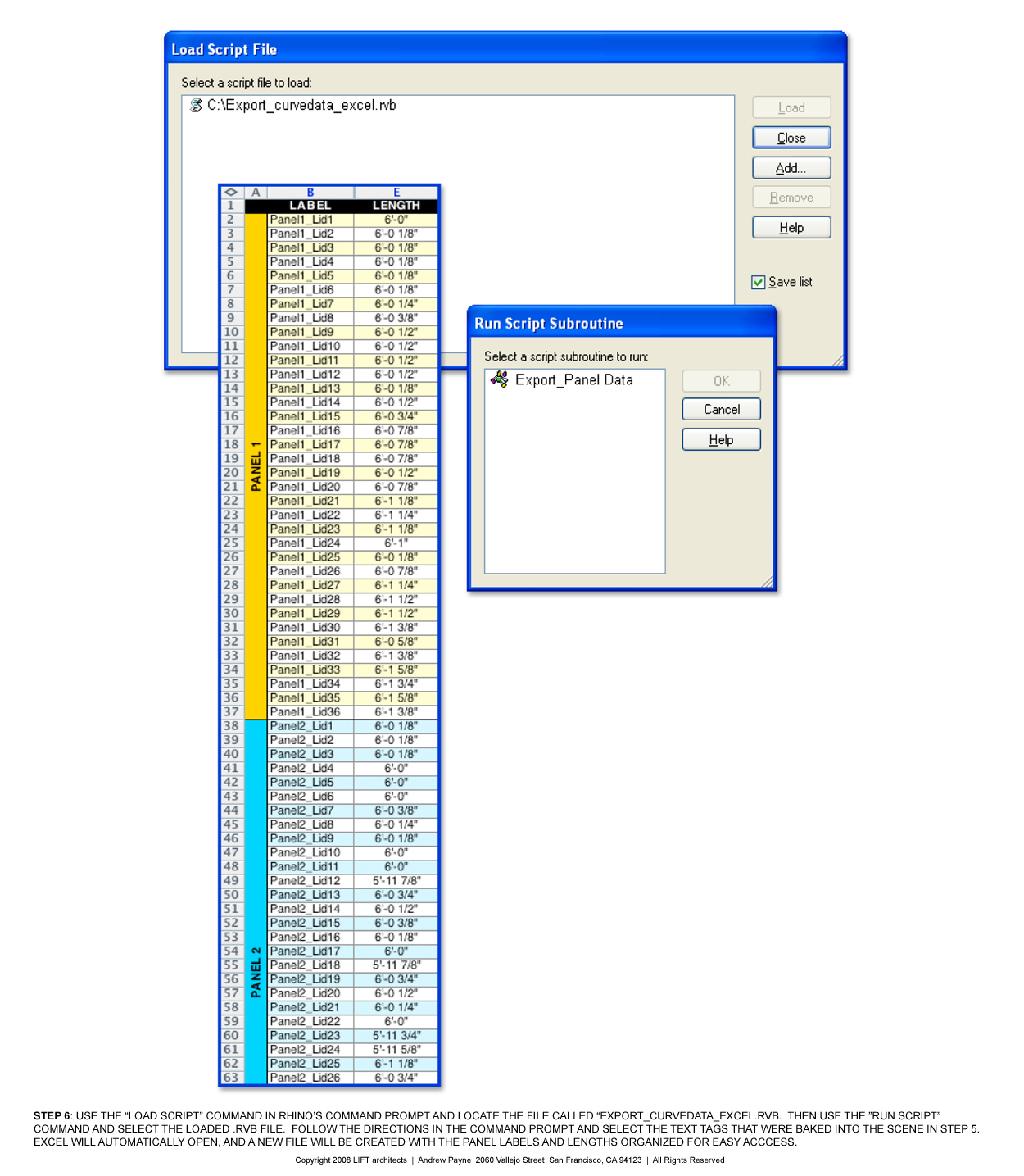 Step 6: Once all of the text tags have been baked into the scene, use the "Load Script" command and locate the rhinoscript called "Export_curvedata_excel.rvb". The use the "Run Script" command and select the loaded rhinoscript from the menu. Follow the on screen directions in the command prompt and select all of the text tags. Excel will automatically open, and a new file will be created with the panel labels and lengths organized for easy access. Within Excel you can convert the length stored from Rhino (rounded to the nearest one thousandth) into a more managable dimension using feet and inches and a specified tolerance. Click image for more detail.
"Put a Lid on It" Party
With a turn out of 21 people for our fourth "Put a Lid on It" volunteer party, we were able to get a great deal accomplished. It has really been an amazing process with an unbelievable response from the community. We've now completed 29 out of 84 panels (over 1,000 lids finished) for the mason jar lid ceiling. If you're interested in taking part in our exhibition pavilion for the Slow Food Nation event being held in Fort Mason on Labor Day weekend, please stop by our office any Thursday evening (6:30-9:00) or Sunday evening (4:00-7:00) between now and the event date. Thanks again for all those who have contributed so far to make the Pickle Pavilion become a reality! Below are a few miscellaneous pictures from the whole fabrication process.


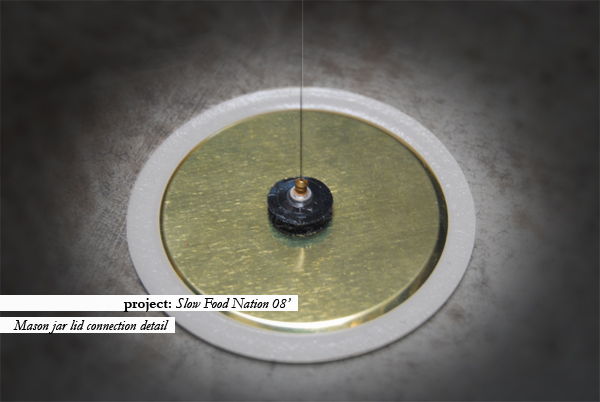
Lid of Lids Mockup
Our team finally decided to go forth with our second full scale mockup of the suspended mason jar ceiling and here are a few shots from this weekend's test. I was pretty satisfied with our connection detail between the mason jar lid and the fishing line that we are using to suspended the lid from the peg board ceiling. We were able to come up with a system that eliminates all knot tying by threading the fishing line through the back of an ear ring and sandwiching it between the ear ring back and the back side of one piece of a circular velcro strip. It did take a little practice, but overall the system seems to work pretty efficiently. The velcro also allows for some adjustability which will hopefully work in our favor once we begin final assembly. 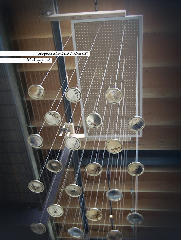
Animaris Rhinoceros Mechanism
With a background in science from the University of Delft in Holland, Theo Jansen's kinetic sculptures inspire a sense of wonder at the complexity of nature. For the past 10 years, he has explored the idea of making mechanisms that walk in the wind, ultimately generating a series of "beasts" that rome the beaches living out their own lives. While there are a full series of sculptures, I found the Animaris Rhinoceros sculpture particularly interesting. I decided that I would need to create an interactive digital model of the system to understand the mechanics behind the design. The digital model uses Inverse Kinematics and Bones in 3D Studio Max to create the connections needed for the machine. Essentially, each side of the model is rigged with Inverse Kinematic solvers and then parented to an invisible "Crank" in the middle. By rotating the center crank (named Crank1) around the Y-axis, the system begins to "walk" forwards or backwards depending on the rotation of the crank. Once the initial rig is created, it can be instanced to create the full system as shown in Mr. Jansens actual sculpture.
Download Animaris Rhinoceros.zip (3D Studio Max 9 size: 39k)
Note: This software and its documents are in the public domain and are furnished "as is". The author, Andrew Payne, makes no warranty, expressed or implied, as to the usefulness of the software and documentation for any purpose. This work is licensed under a Creative Commons Attribution-Share Alike 3.0 United States License. http://creativecommons.org/licenses/by-sa/3.0/us/
Johnny Chung Lee - Head Tracking and Interactive Displays
It's been a while since I have seen something that has truly changed the way I look at technology... But a few of the projects designed by Johnny Chung Lee, a Ph.D. graduate student at Carnegie Mellon's Human-Computer Interaction Institute, are quite remarkable in their ingenuity. While many of his projects are applicable becuase of their use of products that are readily available, two projects of his stand above the rest. If you haven't seen these yet, make sure to check out his demonstrations of "Head Tracking for Desktop VR Displays using the Wii Remote" and "Foldable Interactive Displays".
Head Tracking for Desktop VR Displays and other Wii Projects
Projector-Based Location Discovery and Tracking with Foldable Displays
About Johnny Chung Lee
St. Helena Residence - Update
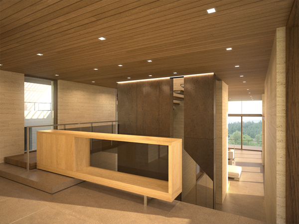
I just completed a new rendering for a house that I am working on in St. Helena, California for Sagan Piechota Architecture. The rendering has been updated to show the current material selections as well as a new cast bronze paneled wall in the entry of the main house. I am currently researching fabrication techniques on how to cast large panels of bronze, as well as finishing a cost analysis for our client. Below are a few of the most recent construction photos of the house.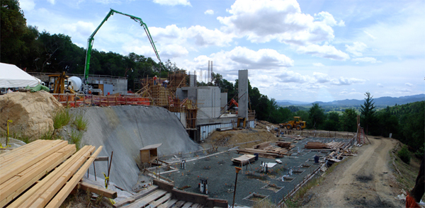
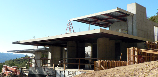
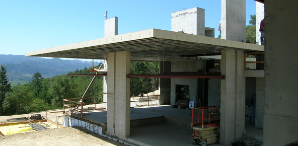
All images copyright 2007 by Sagan Piechota Architecture
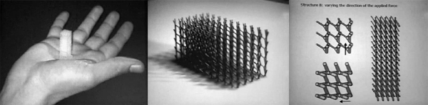
Tensegrity Wall
After a long time coming, I finally decided to continue my research on actuated tensegrity systems. I had already created a fully rigged tensegrity module whose compression member's rotation was driven by the distance from the apex of the system to the midpoint. This distance was wired to a slider in the 3D Max file, so the user can easily drive the system by the use of one simple device. However, to complicate matters a little bit, I decided it would be more interesting to rig these modules up into a system, or a wall type structure where all the modules were connected and thus getting more displacement out of the design. Through a little more math and a lot more time, I was able to create a 4x4 wall system that is fully controlled by the same slider that controls the vertical movement of an actuator inserted in the middle of each module (which would ultimately control the distance from the apex to the midpoint). This system could be configured to work with a sensor so that the structure could change shape according to various environmental stimuli.
Download Tensegrity Wall.zip
Note: This software and its documents are in the public domain and are furnished "as is". The author, Andrew Payne, makes no warranty, expressed or implied, as to the usefulness of the software and documentation for any purpose. This work is licensed under a Creative Commons Attribution-Share Alike 3.0 United States License. http://creativecommons.org/licenses/by-sa/3.0/us/
Responsive Material / Responsive Structure
Make sure you take a look at the lecture given by Sean Hanna at the Subtle Technologies event held at Toronto University. While he readily admits that the manipulation of individual molecules for the production of nano-scale materials is still out of the realm of reality, his focus has been to study micro-structures (at the scale of the millimeter instead of the nanometer) and genetic algorithms in order to create learning materials. His research is readily applicable at other scales as well. Click here to go to the lecture.
Cantilever Bookshelf


This is a remake of a cantilevered bookshelf I made few years ago. The concept is the same as the previous version, however I've simplified the design and eliminated any kind of connection pieces between the counter weight and the steel plate. Essentially, this bookshelf can be made with one precast concrete counter weight, one structural steel channel, and one custom piece of sheet steel slotted down the middle to accomodate and adjustable bookend (not shown) to stop the books from toppling over as they are placed farther down the shelf.
Wine Bottle Wall
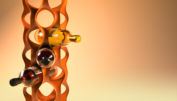
Here is a model I've been working on to develop a wall system that could be digitally fabricated and used to store wine bottles in a unique way. The module, seen on the right, was develped using the Sculpture Generator 1 by Carlos H. Sequin, at UC Berkeley. The modules could be stacked and repeated to form a series of wine rack columns, or duplicated to form a unique wall system.
The Machinery Exchange v1.0
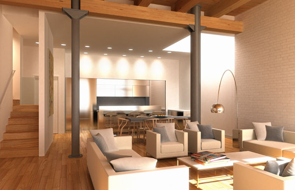
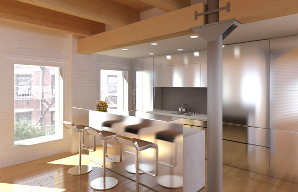
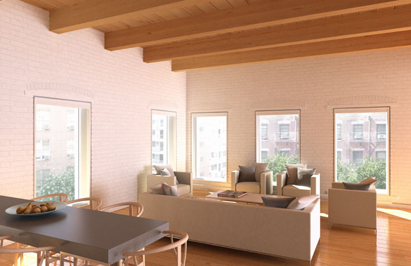
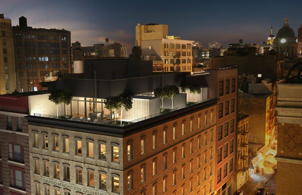
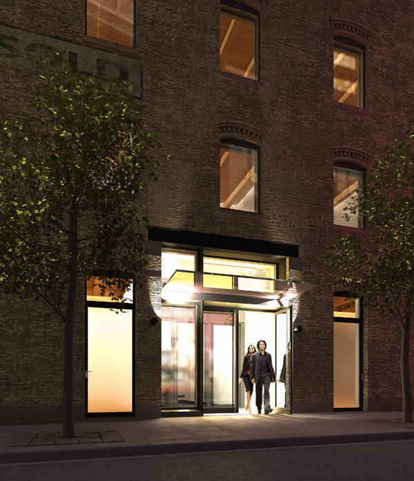
Here are a few of the final images that Alan Silverman and I finished for a new condo project opening up in New York City. The post below shows new construction photos of the project that was designed by Mark Dubois and Ed Rawlings, and developed by Max Protetch. There are other visualizations that we completed also posted on the project website, so make sure to check it out at http://www.machineryexchangecondo.com/