![[LIFT] architects](/storage/layout/Header_025.png)
Design X

What is Design X?
At ICFF you can get in the digital fabrication game through DesignX, a series of hands-on workshops bringing together leading experts from digital design and fabrication. These workshops—on the topics of Digital Tools, Fab On-Demand, and Cloud-Based Apps—will show you how to harness cutting-edge technology to bring your ideas to reality.
Who should attend?
DesignX is geared toward innovative designers, manufacturers, representatives and anyone who is interested in learning about the digital tools and technology trends that are revolutionizing design today. Join in for an inspiring four days of educational programming and networking events at ICFF 2013.
About this workshop?
I'm excited to be teaching two sessions on Sunday, May 19th as part of this year's Design X event. The first is a Introduction to Physical Computing with Arduino where we'll learn the fundamentals of Physical Computing including basic circuitry, different types of input sources, and output options, and how to integrate all three to create a working prototype.
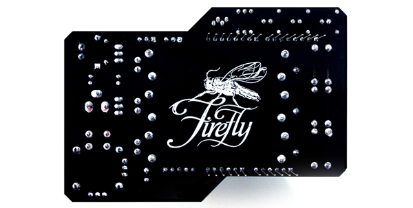
The second session is an Introduction to Responsive Design using Firefly. In this session we'll learn new Interactive Prototyping techniques using the Firefly plugin for Grasshopper which facilitates real-time communication between the digital and physical worlds – enabling the possibility for you to explore virtual and physical prototypes with unprecedented fluidity.
Click Here to Learn More About DesignX and Many Other Exciting Workshops!
New Publications
 AOP
in AD, Interactive, News, Research, publications
|
AOP
in AD, Interactive, News, Research, publications
|
 Post a Comment
|
Post a Comment
|
 1 Reference
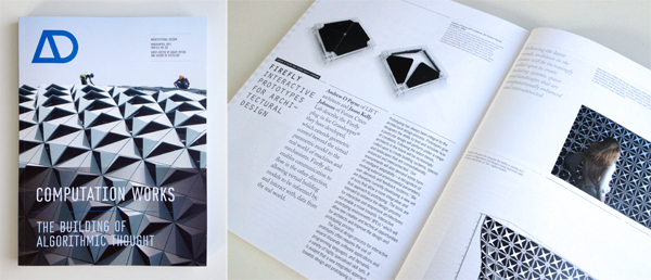
If you haven't already done so, make sure to check out this months issue (April 2013) of Architectural Design (AD) titled Computation Works: The Building of Algorithmic Thought. Edited by Xavier De Kestelier and Brady Peters, this issue focuses on emerging themes in computational design practices, showcasing built and soon-to-be-built projects and providing a state of the art in computational design.
In addition to some amazing articles written by Daniel Davis, David Rutten, Daniel Piker, Giulio Piacentino, Arthur van der Harten, Thomas Grabner and Ursula Frick, and many more... it also features an article that I co-authored with Jason K. Johnson titled Firefly: Interactive Prototypes for Architectural Design. Make sure to check it out, as it's definitely worth the read!
In addition, make sure you also take a look at the book Prototype! edited by Julian Adenauer and Jorg Petruschat which was published by Form+Zweck last summer (2012). Written by leading individuals at world renown design labs and research centers, this book offers a unique compilation of articles centered around the topic of advanced forms of prototyping. In my article, IDE vs. IPE: Toward and Interactive Prototyping Environment I discuss the need to shift toward a more visually oriented Interactive Prototyping Environment (IPE) which addresses the limitations found in the existing IDE paradigm and opens up creative new opportunties for artists and designers.

Facades+ Interactive Surfaces Workshop

NEW YORK, NY | NEW YORK CITY COLLEGE OF TECHNOLOGY | INTERACTIVE SURFACES WORKSHOP | APRIL 12, 2013
I am excited to be teaching a one-day Interactive Surfaces workshop for the upcoming Facades+ Conference being held in New York City on April 11th-12th. The event has an amazing line up of speakers and workshops which are being taught by some of the industries leaders including: Robert Aish (Autodesk), Nathan Miller (Case), Skylar Tibbits (MIT + Ted Fellow), Neil Meredith (Gehry Tech), and John Sargent (SOM).
The Interactive Surfaces workshop will concentrate on producing facade prototypes that are configurable, sensate, and active. The facade of a building is the liminal surface across which information and environmental performance is frequently negotiated. Given dynamic context of our built environment; the facade must be capable of intelligent adaptation over time.
In this workshop, we'll be focusing on new hardware and software prototyping techniques; primarily focusing on a wide range of sensing and actuation modalities in order to build novel interactive devices. Using remote sensors, microcontrollers (Arduino), and actuators, we will build virtual and physical prototypes that can communicate with humans and the world around them. Using both Grasshopper and the Firefly plug-in, you will learn how to create intelligent control strategies for interactive or responsive facades.
The participants who sign up for this workshop will also be the first to get their hands on the new Firefly Interactive Prototyping Sheild which I have been developing. This shield provides access to a number of built-in, ready-to-use sensors and actuators including: 3 linear sliders (potentiometers), a light sensor, a two-axis joystick, 3 push buttons, a red LED, a yellow LED, a Green LED, and a Tri-color LED, 2 servo connections, and a high-voltage MOSFET circuit capable of driving lights, valves, DC motors, etc. Each participant will not only walk away with a kick ass new hardware kit, but valuable knowledge in how to create new types of interactive prototypes!

Printing Material Distributions
AOP
in 3D Printing, Architecture, Objet, Research
|
Post a Comment
|
1 Reference
written by: Panagiotis Michalatos and Andrew Payne
Most digital design involves surface modeling. Even so called “solid” modeling software is based on representations where a “solid” is that which is enclosed by a set of boundaries (known as boundary representations or ‘Brep’ for short). While digital representations of solid objects are often treated as homogeneous and discrete entities, the reality is somewhat different. In the real world, material distributions are continuous and varied. Yet, with regard to architectural components, the variability of material within a volume is usually concealed (ie. porosity of bricks, various types of reinforcements for concrete structures, etc.) and is rarely taken into account during the early design process. With the advent of 3d printing techniques, a new possibility emerges - allowing us the ability to reconsider the aesthetic and mechanical properties of visible reinforcement. In this post we discuss a structural optimization method in conjunction with the possibility of treating structural elements as living in a material continuum that renders objects and reinforcements fuzzy.
Topology optimization is a form finding technique which seeks to optimize a certain material distribution with given boundary conditions (ie. types of supports and loads). It departs from standard form finding techniques in that it assumes that a volume of virtual material can continuously vary its stiffness or density throughout space. Until now the final step of this process involved a cut off threshold; a sharp boundary of hard solid material and void. However intermediate steps of topology optimization suggest grey zones of intermediate material stiffness. These results were usually discarded as unrealistic from a fabrication point of view. With multi material printing we can experiment and speculate about possible realizations of such fuzzy structural objects. The analysis and design of the experiments presented here were carried out using the tools Topostruct (a standalone application) and Millipede (a plugin for Grasshopper) created by Panagiotis Michalatos and Sawako Kaijima.
Three experiments were conducted: the first is the design of a chair using standard topology optimization techniques and interpretation (single solid material), the second was a new type of truss/beam element with fuzzy visible reinforcement (soft transparent material encasing gradations of a harder bone-like structure), and the last one was a similar interpretation to the cantilevering slab which produces patterns reminiscent of a leaf (since leaves solve the same structural problem).
Example 1: A chair
The chair example uses topology optimization to gradually remove material from a solid volume on which the actions of a person seating are applied (ie. vertical and horizontal loads for the seating position). 3d printing allows us the ability to materialize the intricate structures that emerge especially around moment connections.
;)
Figure 1: from left to right: Initial boundary volume setup for chair configuration and successive steps of material redistribution through topology optimization. Darker areas designate denser material.
;)
Figure 2: Features of the chair become more refined during each subsequent step through the topology optimization process.
;)
;)
Figures 3 & 4: Converged geometry of the topology optimization process.
Example 2: A fuzzy truss
For the second experiment we revisited one of the simplest forms from engineering textbooks. The truss like structures that act like bridges supporting a distributed load at their two end points. However, in this example, the topology optimization routine was set up in such a way that instead of a solid object, it yielded a continuous variation of material stiffness. Using Objet’s multi-material printing technology, we were able to develop a gradated structure using a transparent rubbery material and a hard white material (and the gradations in between the two) to achieve an outcome that looks, feels, and structurally acts like a fuzzy reinforced structure.
;)
Figure 5: [top left]: Setup of boundary conditions for simple bridge [main volume + supports at the two lower corners and distributed load at the top]. [top right]: Deflected shape of solid material after load application. [bottom images]: stress distribution and topology optimization contours. Inner contours represent regions where stronger material is required.
;)
Figure 6: Topology optimization drives material redistribution within the volume of the truss. A fuzzy truss shaped beam reinforcement gradually emerges.
;)
Figure 7: A 3d printed diagram showing the distributed load on top and the two supports on either end plus the optimal shape of the reinforced region.
;)
Figure 8: Using multi-material printing technology, a fuzzy bone-like structure can be created using gradients between a transparent rubbery material and an opaque hard material. In this way the actual outcome of the topology optimization process can be directly materialized.
Example 3: A leaf-slab
Our final experiment involved the reinterpretation of a different traditional system - the cantilevering slab. The distributed load over this horizontal plate puts similar requirement to that of a leaf and topology optimization yields branching structures reminiscent of the venation found in leaves.
;)
Figure 9: A fuzzy branching pattern emerges when a distributed load is applied to a cantilevering slab from a single support, resembling the vein patterns of leaves.
;)
Figure 10: A 3d printed diagram showing the cantilevered load and support structure.
;)
Figure 11: Multi-material printing allows us to materialize semi-rigid and semi-transparent fuzzy structural systems as a kind of gradual reinforcement embedded in the material where the boundaries between softer and harder parts are blurred.
The ability to continuously vary the stiffness and transparency of material will allow us to rethink design techniques and technologies, software tools, and analysis methods beyond the surface modeling paradigm. In the scale of product design this is already possible thanks to technologies like multi-material 3d printing. Such experiments will be valuable precedents when speculating about new types of continuous and fuzzy building systems.
This research was generously supported by Objet Technologies. For more information about their 3d printing technology, visit http://www.objet.com.
Synthetic Landscapes Workshop
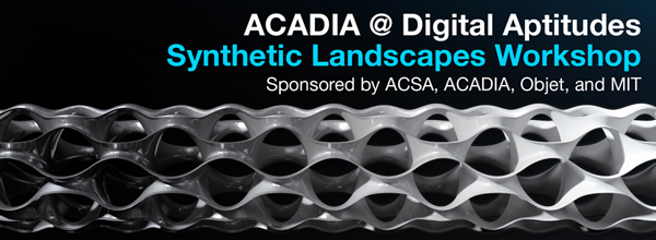
BILLERICA, MA | OBJET HEADQUARTERS | SYNTHETIC LANDSCAPES WORKSHOP | FEB 29TH-MAR 1ST, 2012
This intensive two-day workshop at the Objet Headquarters in Billerica, MA will provide workshop participants the opportunity to work with a team of expert consultants, to hone their digital and prototyping skills, to experiment with a range of digital production tools, and to design and fabricate a unique set of components that negotiate a range of material gradients across a field condition. Through iteration, participants will generate and fabricate components (parts) to form a larger network (whole). The goal of this workshop is to combine technological precision (Objet – Connex) and pedagogical creativity (curriculum) to explicate the creative potentials of both the various forms of software and materials-based investigations that could be replicated in curriculum.
The results of the workshop will be showcased at the Boston Park Plaza, formally presented during a Special Focus Session on Friday, 02 March during the 100th ACSA Annual Meeting, and be part of a traveling exhibition that will circulate North America in 2012.
Consultants:
*Gregory Luhan (ACSA/ACADIA organizer)
MIT: Justin Lavallee, Neri Oxman, and 2-4 MIT student assistants
ACADIA: *Gil Akos, *Kyle Miller, *Ronnie Parsons, *Andy Payne
* Designates Workshop Leaders
Schedule:
Wednesday, February 29th
8:00am: Buses leave for Objet Headquarters
9:30am: Orientation and introduction of the project, tour of labs, presentation of Objet machine
12:00pm: Lunch Provided
12:30–6:00pm: Work in small groups, with consultation from instructors
6:00–7:00pm: Dinner Provided
7:00–10:00pm: Shop/lab access
10:00pm: Buses return to the hotel
Thursday, March 1st
8:00am: Buses leave for Objet Headquarters
9:00–12:00am: Continued work
12:00am: Lunch Provided
12:00–3:00pm: Final shop/lab access
3:00–6:00pm: Buses leave Objet Headquarters - participants take projects to Park Plaza for display in the ACSA Annual Meeting Exhibit Hall.
6:00–7:30pm: ACSA Annual Meeting Keynote Panel on Digital Technologies by: Sanford Kwinter. Jeff Kipnis, Sylvia Lavin, Katheryn Gustafson, Mark Burry
7:30–9:00pm: Reception in the Exhibit Hall (featuring the final designs by the workshop).
Friday, March 2nd
ACADIA @ Digital Appitudes | Synthetic Landscapes
Special Focus Session to discuss pedagogical implications of the workshop. Panelists include team leaders, workshop attendees, and Piet Meijs.
Using the Digital Aptitudes workshop hosted by Objet as a critical point of departure, this moderated session will focus on linking the pedagogical to the technological. Short presentations by panelists Kyle Miller, Andy Payne, Gil Akos, Ronnie Parsons, Justin Lavallee, Piet Meijs, and Gregory Luhan will frame the conceptual underpinnings of workshop as part of an embedded, participatory, and replicable art-to-part curriculum developed with Neri Oxman. The presenter’s own research into areas including flexible form manufacturing, site malleable construction, building performance, and blended materials research will align the concept-to-completion workshop outcomes as logical extensions of an otherwise technologically-driven and application-based synthetic ecology.
For more information about this workshop and Registration information visit:
A Five-Axis Robotic Motion Controller For Designers
AOP
in ACADIA, Fabrication, Firefly, Robotics, Writings
|
Comments Off
I'm excited to release more information about a paper I wrote titled A Five Axis Robotic Motion Controller for Designers which was selected for publication and presentation for this year's ACADIA 2011 Conference: Integration Through Computation held in Banff, Canada from October 13th-16th. Click here to download the full paper.
This project aims to bring physical input and output closer together through the design purpose-built tools for fabrication, which hopefully leads to many new creative opportunities for designers. Working from observations about the way architects design, this project explores the development of a novel 3D drawing tool or customized 5-axis digitizing arm that takes real-time input and translates movement patterns directly into machine code for robotic fabrication. An improved workflow for robotic simulation was also developed as part of this project; using design tools that are already familiar to architects and designers, such as Rhino and Grasshopper. The purpose of this project was not to suggest that this new workflow is a ready-made solution to replace the existing robotic fabrication process; rather I hope that this work is seen as a proof of concept that could enable wider use of digital fabrication tools by architects and designers.
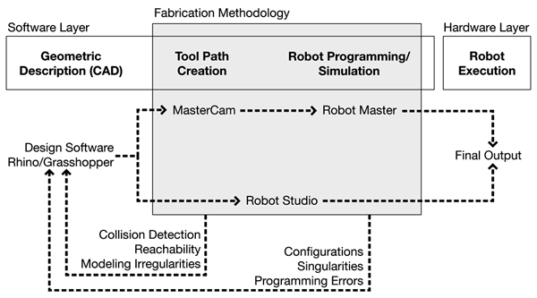
The existing design-to-fabrication workflow for industrial robots (seen above) has traditionally been a slow and cumber-some process, especially for designers. Machine tooling, kinematic simulations, and robotic movement programming often require intimate knowledge of scripting and manufacturing processes, all of which limit the utilization of such tools by the 'typical' architect/designer.
In the traditional robotic fabrication workflow, there is often a discrepancy between the original design intent and the final output, primarily because there is an intermediate step where the designer has to hand off a digital model to a fabrication consultant who has more intimate knowledge of the specific robotic CAM software and the fabrication process in general. Typically, this consultant will use programs such as Robot Studio or Master CAM to create the necessary tool paths for the design, however this process can often take a great deal of time. And, if during this process, modeling irregularities are found or fabrication problems arise due to reachability or collision detection issues, then the entire process must start anew.
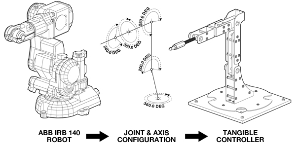
Conceptually, this project started very simply. I began by looking at the joint and axis configurations of the ABB-IRB 140 robot, one of the six axis robots available in the Harvard robotics lab. The design challenge then, was to design a tangible controller around these constraints. By using the same joint and axis configurations, the digitizing arm has a one to one relationship with the larger industrial robot. It is very intuitive. A user immediately grasps the idea that when they move the digitizing arm in a certain way, the robot will respond in kind.
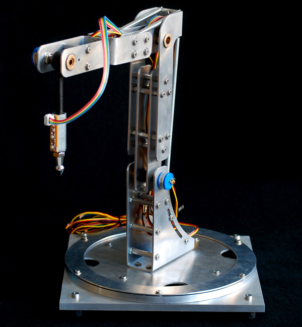
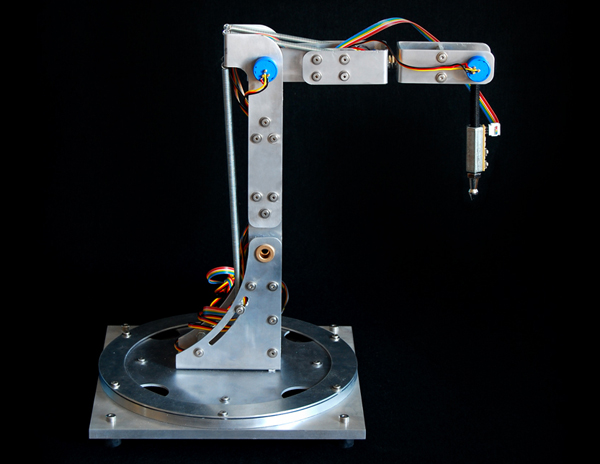
Outside of the development of a new robotic workflow, one of the primary goals of the project was to minimize costs. Given that all of the parts for this project were paid for out of pocket (a student's pocket), creating a low-cost solution was of utmost importance. But, beyond my own personal economic restrictions, I wanted this project to be seen as a do-it-yourself solution - something that could be built in any garage or workbench using easily purchased hardware parts and sensors and a few custom fabricated pieces. The entire controller, shown here, was built for less than $200 dollars. The aluminum body was water jet cut and all of the hardware were pieces that could purchased from local hardware stores or online retailers. All of the sensors, including the five high-precision potentiometers (shown here as the small blue knobs sticking off of the aluminum body) and the two digital sensors on the tool tip were also purchased from online retailers and were chosen because of their affordability.
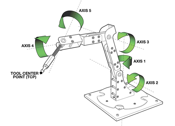
To create a real-time robotic simulation, data from each of the embedded sensors on the tangible controller are streamed into the computer using a plug-in for Grasshopper that I have also been developing called Firefly. Among other things, Firefly enables the use of real-world data, acquired from various types of sensors or other input devices to explicitly define parametric relationships within a Grasshopper model. In this project, sensor information is used to create a forward kinematic robotic simulation. Forward kinematics describes one type of solution for determining robotic positioning. If given all of the relative angles of each joint and the lengths of each leg; the tool tip (also known as the end effector) can be found by performing a series of matrix transformations on each body in the robotic mechanism. In this case, each of the potentiometers will return a 10-bit number between 0 and 1023. These particular potentiometers were able to rotate up to 340º, so the angle between each joint can be found by simply multiplying the current sensor value by the sensor step size. These angle values are used to perform a matrix transformation on each of the robotic legs, ultimately giving you the precise position of the tool center point. And, once you know the location of the end effector, you can record this data over time to create real-time robotic tool paths.
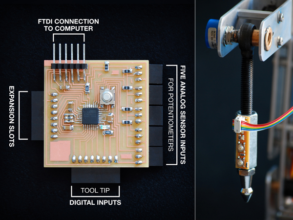
In addition to the five high-precision potentiometers, the digitizing arm is equipped with a tool tip circuit board with two push button controls. These allow the user to easily record or reset the digitized information on the fly. I also designed and built a customized circuit board (on the left) which processes all of the sensor information and sends a formatted string of information over the serial port to the virtual parametric interface.
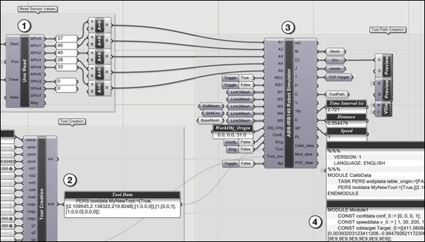
The Grasshopper definition is relatively straight forward. The Firefly Read component parses of the sensor information being sent directly from the microcontroller circuit board. There is a custom component written in VB.NET (seen in item number 2), which creates the necessary tool data. The data from both of these components are fed into another custom component which calculates the forward kinematic solution and outputs the position of each leg, creating a real-time preview of the robot moving in the Rhino viewport. In addition, the robotic simulator also returns all of the RAPID code, or the robotic programming language used by all of the ABB robots, to move the actual robot in the same manner as the forward kinematic preview.
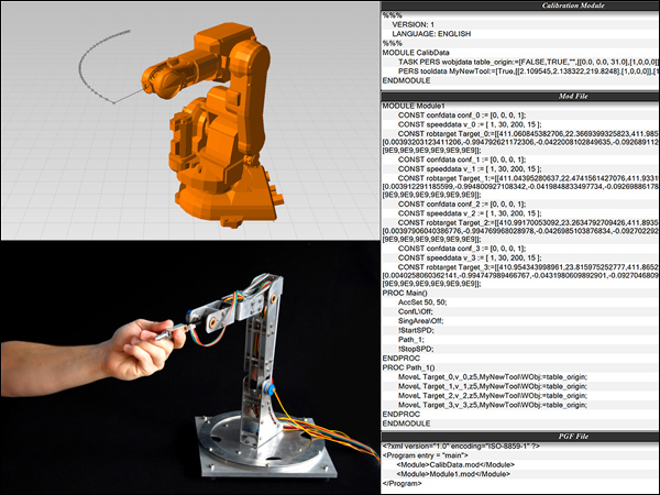
The custom robotic simulation component written inside of Grasshopper outputs all of the necessary RAPID code to control the actual robot. There are two methods by which this can be done. First, all of the digitizing information is recorded and formatted into a composite data type called a robtarget. Each robtarget is defined by its name, absolute position as XYZ coordinates, rotation and orientation of the robot as four quaternion values, and its joint configurations. Each robtarget is given a unique identification each time the solution is recomputed. Then the movement commands are created to tell the robot specifically how to get to each robtarget. Once the program has been written, it can then be saved to a file on disk and uploaded to the robotic controller to be played back. An alternative method is to stream the angle information from the digitizing arm directly to the robot through a network cable. In this method, a program is uploaded to the robot which tells it to sit and wait for any information being sent directly from the Grasshopper definition (which can be seen in the video above).
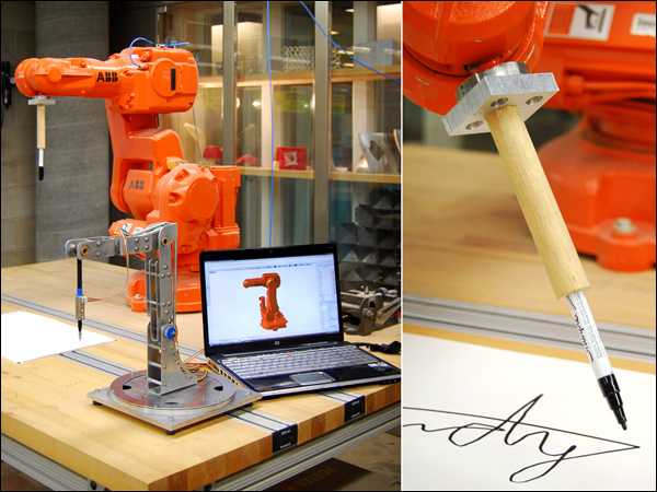
As of today, there have only been a limited number of test runs using the five-axis robotic controller, however, the initial tests suggest that the proposed direct-to-fabrication process could prove to be a viable alternative to existing robotic workflows. One of the first tests I tried was attaching a custom designed pen tool to the robot to see if the drawing movements of the digitizing arm would match those of the robot. And while spelling your name isn't the most exciting demo, it did show some of the potential available with this process. Because virtually any end effector can be attached to the end of the robot, the design opportunities are endless. And because the tangible controller has a one-to-one relationship with the larger industrial robot, designers immediately understand that their drawing motions will be converted directly into robotic movements, creating a very intuitive interface.
Although there has been considerable progress made in the digital tools used to control robots, I'd like to close by reiterating the fact that there is an identifiable problem in the existing design-to-fabrication process. I would like to propose an improved workflow for robotic fabrication. It is the hope of this project that the physical articulation of embodied input and output through purpose-built tools for fabrication can allow for wider adoption by and new creative opportunities for architects and designers. In turn, I hope this will help re-establish the relationship between designers and the physical fabrication process.
Acknowledgments:
I would like to thank Harvard professors Martin Bechthold and Pangiotis Michalotos as well as Neil Gershenfeld from MIT's Center for Bits and Atoms for their support during the development of this project.
ACADIA 2011: Integration Through Computation
![]()
I am very happy to announce that my full-paper titled A Five-Axis Robotic Motion Controller for Designers has been accepted for presentation and publication in the conference proceedings of the ACADIA 2011 conference to be held at the Banff Center, Calgary Canada from Oct. 11th-16th, 2011. You can find out more about the entire line-up of speakers on the ACADIA website. I'll also be releasing more information about this project (and paper) very soon, so stay tuned.
I would also like to mention that I will be teaching a two-day workshop on physical computing (using Arduino, Grasshopper, and Firefly) as part of the ACADIA pre-conference workshop series. This fast-paced workshop will focus on hardware and software prototyping techniques. For more information, see the workshop description below.
Workshop Description:
In 1991, Mark Weiser published a paper in Scientific American titled, The Computer for the 21st Century, where he predicted that as technology advanced, becoming cheaper, smaller, and more powerful, it would begin to "recede into the background of our lives" - taking a more camouflaged, lifestyle-integrated form. He called this Ubiquitous Computing (Ubicomp for short), or the age of calm technology. There have been numerous examples to support Weiser's claim, including Natalie Jeremijinko's "Live Wire" project (1995), the Ambient Orb (2002), or the Microsoft Surface Table (2007) to name just a few.
In 1997 Hiroshi Ishii expanded Weiser's idea in a seminal paper titled Tangible Bits where he examined how architectural spaces could be transformed through the coupling of digital information (bits) with tangible objects. Where Wieser’s research aimed to make the computer ‘invisible’ by embedding smaller and smaller computer terminals into everyday objects, Ishii looked to change the way people created and interacted with digitally augmented spaces.
Both Weiser and Ishii have had a significant impact on the development of physical computing, a term used to describe a field of research interested in the construction of physical systems that can sense and respond to their surroundings through the use of software and hardware systems. It overlaps with other forms of tangible computing (ie. ubiquitous, wearable, invisible) and incorporates both material and computational media, employing mechanical and electronic systems.
Interest in physical computing has risen dramatically over the last fifteen years in the fields of architecture, engineering, industrial design, and art. Designers in the future will be called upon to create spaces that are computationally enhanced. Rather than simply design traditional buildings and then add a computational layer, it is better to conceive and design this integration from the outset. A review of the literature reveals that there are no established methodologies for designing architectural spaces as smart or intelligent spatial systems. As such, it is clear that a new multidisciplinary approach is needed to bring together research in the fields of interaction design (IxD), architectural design, product design, human computer interaction (HCI), embedded systems, and engineering to create a holistic design strategy for more livable and productive spaces. Preparing architectural designers for these challenges demands a range of knowledge, skills, and experience well beyond the traditional domain of architectural education. This workshop in Physical Computing at the ACADIA 2011 conference is in line with the conference theme of Integration Through Computation.
Dates:
2011.October.11 | Workshop Day 1 at University of Calgary
2011.October.12 | Workshop Day 2 at University of Calgary
Software:
All students will be required to bring their own laptops preloaded with the latest versions of Rhino, Grasshopper, and Arduino. The latest build of Firefly will be provided to all workshop participants. Trial software will also be made available.
Hardware:
Given the nature of the workshop, each student will be required to bring a small set of hardware components to begin their physical prototypes. There are many different packages to choose from, but the following are recommended:
Starter Pack
Arduino Starter Pack or equal [includes the new Arduino Uno Atmega328, Protoboard, and a good selection of starter components]. 2 Standard Servo Motors similar to these: Adafruit or Hi-Tec from Servocity.
High-End (Recommended)
Arduino Experimentation Kit v1.0 or Sparkfun's Inventors Kit for Arduino [includes the new Arduino Uno Atmega328, Prototyping bundles, and a great selection of starter components]. 2 Standard Servo Motors similar to these: Adafruit or Hi-Tec from Servocity.
Students are encouraged to bring other components if they have them, but the packages should serve as a good starting point.
Registration:
Click here to find out more information regarding the ACADIA 2011 conference schedule.
Hybrid Prototypes Workshop
NEW YORK, NY | ARDUINO, GRASSHOPPER, & FIREFLY | SEPT 24TH-25TH, 2011
Studio Mode | modeLab is pleased to announce the next installment of the coLab workshop series: Hybrid Prototypes. As a follow-up workshop to the coLab workshop held in January 2011, Hybrid Prototypes is a two-day intensive design and prototyping workshop to be held in New York City during the weekend of September 24-25.
Description:
As architects and designers, we make things and build objects that interact with other objects, people, and networks.We're constantly seeking faster and more inexpensive methods to build prototypes, yet we are frequently hindered by practical and time consuming factors that arise in the process of bringing our ideas to life. Firefly is the new paradigm for interactive hybrid prototyping; offering a comprehensive set of software tools dedicated to bridging the gap between Grasshopper (a free plug-in for Rhino) and the Arduino micro-controller. It allows near real-time data flow between the digital and physical worlds – enabling the possibility to explore virtual and physical prototypes with unprecedented fluidity.
This fast-paced workshop will focus on hardware and software prototyping techniques. Using remote sensors, microcontrollers (Arduino), and actuators, we will build virtual and physical prototypes that can communicate with humans and the world around them. Through a series of focused exercises and design tasks, each attendee will make prototypes that are configurable, sensate, and active. As part of a larger online infrastructure, modeLab, this workshop provides participants with continued support and knowledge to draw upon for future learning.
Attendance will be limited to provide each participant maximum dedicated time with instructors. Participants should be familiar with the basic concepts of parametric design and interface of Grasshopper.
Hybrid Prototypes was conceived through a collaboration between Studio Mode/modeLab and Andrew Payne/LIFT Architects/Grasshopper Primer/ Firefly.
Instructors:
Andrew Payne | Principal, LIFT Architects | Co-Author, Grasshopper Primer | Co-Author, Firefly.
Ronnie Parsons + Gil Akos | Partners, Studio Mode.
Click here to register for the workshop.
Details:
All experience levels are welcome. Participants are encouraged to be familiar with the basic concepts of parametric design and interfaces of Grasshopper and Arduino.
Registration Pricing (limited enrollment) : $550.
Workshop Location : Gansevoort Studio | Meatpacking District, Manhattan.
Workshop Hours : 10AM-6PM.
Examples of Previous Workshops.
Infrastructure:
coLab Workbook | Printed + PDF Documentation
coLab Primers | Annotated Primer GHX Files
coLab Exercises | Annotated Exercise GHX Files
modeLab Fabrication Equipment | CNC High Force Cutter
Topics:
Arduino Micro-controller Hardware
Arduino Control Logic
Firefly Components
Parametric Design Logics
Basic Circuitry
Sensors + Actuators
Software:
All students will be required to bring their own laptops preloaded with the latest versions of Rhino, Grasshopper, and Arduino. The latest build of Firefly will be provided to all workshop participants.
Trial software will also be made available.
Hardware:
Given the nature of the workshop, each student will be required to bring a small set of hardware components to begin their physical prototypes. There are many different packages to choose from, but we recommend the following:
Starter Pack
Arduino Starter Pack or equal [includes the new Arduino Uno Atmega328, Protoboard, and a good selection of starter components]. 2 Standard Servo Motors similar to these: Adafruit or Hi-Tec from Servocity.
High-End (Recommended)
Arduino Experimentation Kit v1.0 or equal [includes the new Arduino Uno Atmega328, Prototyping bundles, and a great selection of starter components]. 2 Standard Servo Motors similar to these: Adafruit or Hi-Tec from Servocity.
Students are encouraged to bring other components if they have them, but the packages should serve as a good starting point.
Dates:
2010.August.24 | Workshop Announced + Registration Opens.
2011.September.24 | Workshop Begins.
2011.September.25 | Workshop Concludes.
As architects and designers, we make things and build objects that interact with other objects, people, and networks. We're constantly seeking faster and more inexpensive methods to build prototypes, yet we are frequently hindered by practical and time consuming factors that arise in the process of bringing our ideas to life. Firefly is the new paradigm for hybrid prototyping; offering a comprehensive set of software tools dedicated to bridging the gap between Grasshopper (a free plug-in for Rhino) and the Arduino micro-controller. It allows near real-time data flow between the digital and physical worlds – enabling the possibility to explore virtual and physical prototypes with unprecedented fluidity.
This fast-paced workshop will focus on hardware and software prototyping techniques. Using remote sensors, microcontrollers (Arduino), and actuators, we will build virtual and physical prototypes that can communicate with humans and the world around them. Through a series of focused exercises and design tasks, each attendee will make prototypes that are configurable, sensate, and active. As part of a larger online infrastructure, modeLab, this workshop provides participants with continued support and knowledge to draw upon for future learning.
Attendance will be limited to provide each participant maximum dedicated time with instructors. Participants should be familiar with the basic concepts of parametric design and interface of Grasshopper.
Firefly + Kinect
Like many people, I've been anxiously awaiting the official release of the Microsoft SDK for the Kinect. Now, that its officially out, I spent some time over the last two weeks working on a set of Kinect related components that I hope to include in the next release of Firefly (1.007). The first component I tried to implement was the Skeleton Tracker... and I have to admit that the result are quite promising. It's surprisingly fast and as long as you stay within the specified range of the sensor, the results are quite good. Using this component I put together two very quick demo videos.
There has been a big push over the last decade to develop novel 3D technology for multimedia displays (whether its new ways for stereoscopic projection, refractive lens, etc.) One of the most successful implementations and inventive (in my opinion) was Johnny Chung Lee's reverse engineering of the Wii sensor bar. Another recent example (and equally impressive) is this hack using the Kinect sensor and head tracking.
The video above is my first attempt to create a real-time 3D display system within Grasshopper using Firefly's new Skeleton Tracker component and some simple camera manipulation. The Skeleton Tracker component outputs a list of points (click here for further explanation). From there, I simply use the Horster Camera Control component (another 3rd party plugin for Grasshopper) to position the camera at the viewers head and the camera target at a point in space locating the Kinect sensor. It really is that easy. Turn on some real-time shadows and you've got a real-time 3D display. It still needs some tweaking but it's pretty fun to play with.
This next demo shows how easy it is to turn gestural movements into physical actuation using an Arduino. The setup is very simple. My z-value of my right hand (basically the height of my hand) controls the brightness value (or Pulse Width Modulation - PWM) of the LED. My left hand controls the servo. When my hand is by my side, the servo goes to position 0 and if I raise my hand above my head the servo moves to position 180. So simple. Of course, this could be expanded to control all sorts of things... perhaps that is next.
Firefly 1.006 New Features
I was extremely excited to announce the official release of Firefly version 1.006 earlier this week. For those who aren't familiar with Firefly, allow me to provide a short introduction. Firefly is a set of software tools dedicated to bridging the gap between Grasshopper (a free plug-in for Rhino), the Arduino micro-controller, the internet and beyond. It allows real-time data flow between the digital and physical worlds and will read/write data to/from internet feeds, remote sensors and actuators, mobile phone devices, the Kinect, and more. There are a lot of new components in this release (including the Arduino Code Generator, Upload to I/O Board, UDP and OSC Listeners and Transmitters, XML Search, and State Detection) that I thought it would be a good idea to put together a few videos showing some of the latest features. So without further ado...
This first video shows the potential of the new Arduino Code Generator and the Upload to I/O Board components. In my opinion, one of the greatest limitations of the previous versions of Firefly was that your Arduino board always had to be tethered to your computer via the USB cable. This was because Firefly communicates back and forth to Grasshopper through serial communication. However, sometimes you just want to use Grasshopper (and its visual programming interface) to prototype your design and then unplug it from your computer to run off external power. Now, you can!
The Arduino Code Generator attempts to convert any Grasshopper definition into Arduino compatible code (C++) on the fly. It works by detecting components that are 'upstream' from the Uno/Mega Write component. The Code Generator checks the component ID against a library of custom C++ functions which then get added to the code if there is a match. The code can be simultaneously saved as a .pde (Arduino Sketch) file to be opened in the Arduino IDE.
In addition, there is also a new Upload to I/O Board component which allows you to upload any sketch (could be from the Code Generator or any other sketch) directly to your Arduino board from within the Grasshopper environment. A lot of stuff happens behind the scenes with this component. Essentially it creates a dynamic MakeFile and calls a shell application to convert the .pde file into a .cpp (C++) file and then into .hex code (machine readable code) to be uploaded to the microcontroller. Note: WinAVR is required to be installed on your machine in order to properly upload sketches to your board. You can download the latest version here.
There are also a lot of great network tools included in this release, including the UDP and OSC Listener and Transmitter components. OSC (Open Sound Control) messages are essentially specially formatted UDP messages which can be particularly handy when you want to send some sort of information across a network (either wirelessly or LAN). OSC messages are particularly useful because each message contains some metadata and a value, giving you more information about what type of data the message contains. These new components open up a whole new world of possibilities by allowing you to send/receive data from smart phones (iphone or android) or by sharing documents among friends or colleagues over a network.
The video above uses the BreathOSC application (free from the iphone app store) developed by Thomas Edwards to simulate wind effects in Grasshopper. Simply breathe into the microphone and an OSC message is sent to a specified IP address on a UDP port. I then simply use the OSC Listener to decode the message and uses its value to create a wind vector to drive the Kangaroo (another 3rd party plugin for Grasshopper) wind simulation. Daniel Piker, the developer of Kangaroo, helped setup this demo... and I have to say... it's quite fun.
Another useful networking application for smart phones is TouchOSC (available for both iphone and android). It supports sending and receiving Open Sound Control messages over a Wi-Fi network using the UDP protocol. You can also create your own interfaces using the TouchOSC Editor and sync them directly to your phone. In this example, I've created a simple layout to control a few LED's, a tri-color LED, and a standard servo using the new OSC Listener in Firefly. This is just a simple test, but the sky is the limit with this type of control over mobile phone interface design.
If you are interested in learning more about Firefly, check out our website at: http://www.fireflyexperiments.com/
The website has a lot of good tutorials and examples to get you up and running in no time. As always, if you have a suggestion or want to send us a comment, you can reach us at info@fireflyexperiments.com
Acknowledgements:
It is without a doubt that this release would not have been possible without the tremendous support from Prof. Panagiotis Michalatos at Harvard's GSD. His guidance over the last 6 months strongly influenced the development of the Firefly_X toolset and I owe him a great debt of gratitude for his assistance. Firefly is built upon the Grasshopper plug-in for Rhino, both developed by Robert McNeel and Associates. The Arduino language syntax is based on Wiring by Hernando Barragan. The Arduino environment is based on Processing byBen Fry and Casey Reas, and is now supported by an amazing team of software and hardware developers that continue to refine and expand its capabilities.
Python for Rhino Primer Now Available
Skylar Tibbits, Arthur van der Harten, and Steve Baer just released an excellent (and free) manual on how to get started programming in Python for Rhino 5.0. This is a must read for anyone interested in learning how automate tasks, make decisions, perform powerful calculations and geometric manipulations using Python and the Rhino CAD environment. Here is a small excerpt from the introduction:
"This primer is intended to teach programming to absolute beginners, people who have tinkered with programming a bit or expert programmers looking for a quick introduction to the methods in Rhino. Rhinoscript (VBscript) has been supported for many years, with a large user group and extensive support material. As well as giving a basic introduction, this primer looks to easily transition those familiar with VBscript into the world of Rhino Python.... Python offers exciting new potentials for programming in Rhino with Object-Oriented functionality, simple syntax, access to the .NET framework and a vast number of user-built libraries to extend Rhino's functionality. The same powerful methods that were previously in VBscript are still available, as well as a ton of other exciting methods and features available natively with Python."
To download the Python for Rhino 101 Primer click here.
Also, Skylar Tibbits will be hosting a 2-hour Introduction to Python webinar on July 22nd. Skylar is a lecturer at MIT's Department of Architecture, the Founder/Principal of SJET LLC and a 2011 TED Fellow. Click here to register for the event.
Projection One
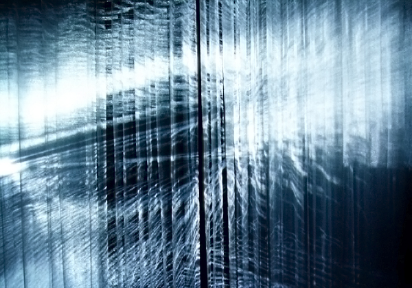
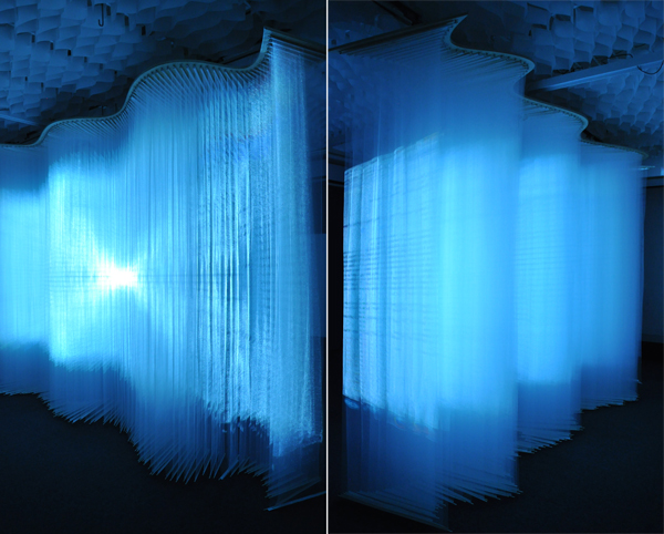
Projection One is an interactive art installation that was recently unveiled at Harvard's Graduate School of Design. Conceived and built by Andrew Payne and fellow GSD student, Eddy Man Kim, Projection One strives to challenge the way in which users perceive projection art. We started by changing the projection surface. Our idea was simple - take the traditional screen and cut it up into strips of variable widths. Then rotate those strips to create a three dimensional surface; adding depth to create a more volumetric or spatial experience out of the projection schemes. The overall surface measured approximately 13'(length) x 9'(height) x 3'(depth).
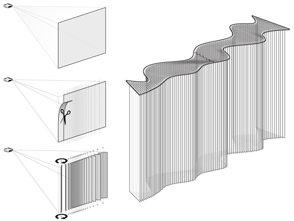
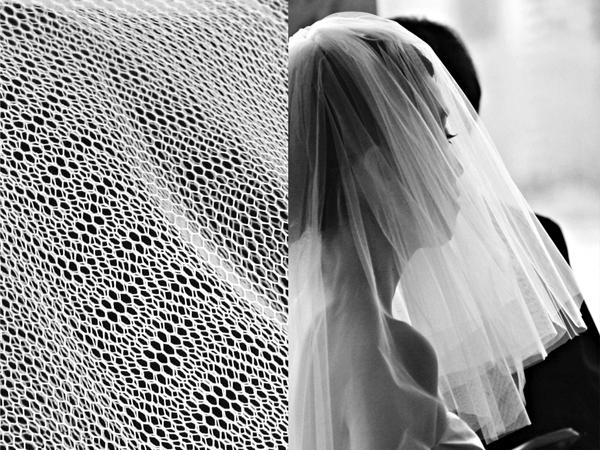
Adding depth to a projection surface only works if the material characteristics of the screen is transparent enough to allow for the light from the projector to pass through. We spent a good deal of time investigating various types of fabrics, and even string; but ultimately found that Tulle provided just the right amount of transparency and material density. Tulle is lightweight net-like fabric traditionally used in wedding veils and other ornamental garments.
Acknowledgements
First, we would like to thank Professor Panagiotis Michalatos. It is without a doubt that this project would not have been realized without his tremendous help and support. All of the visualizations were developed as scripts written in C# and used several of the sawapan motion and audio libraries.
Contact Us
Like what you see or want to know more about how to bring this installation to a city near you? Contact us.