![[LIFT] architects](/storage/layout/Header_025.png)
Entries in Furniture (5)
Surface Patterns With The ShopBot Writer for Grasshopper
 AOP
in CNC, Corian, Fabrication, Furniture, Research, ShopBot
|
Comments Off
AOP
in CNC, Corian, Fabrication, Furniture, Research, ShopBot
|
Comments Off
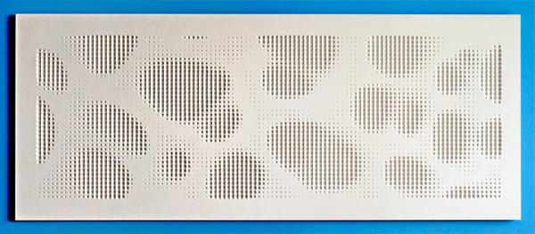
It has been entirely too long since I last posted but that should change over the coming weeks as I've been working on some really amazing projects. To kick things off, I thought I'd share a one week project that I developed to create a dimple halftone pattern on a surface using a custom build Grasshopper definition which writes the all of the G-code (for a ShopBot CNC mill) in real-time. I'll talk more about the fabrication setup below, but first... a little about the concept. I've always been fascinated with the skeletal patterns of Radiolarians (a family of microscopic protozoa that float along the ocean floor). Here's a Wikipedia link for more information. These creatures (perhaps "fossil" is a better word) were made popular by some amazingly detailed and beautiful drawings made by German biologist Ernst Haekel.
I decided to take something very big (the final piece is milled out of a half size sheet (72"x30") of Corian) out of something that is very very small. To get the desired relief pattern, I used a 3/4" V-bit endmill on the CNC mill so that the circle diameter had a linear relationship to the depth of the plunge. Below are some process images showing the original source image and the step needed to take it into final fabrication using the ShopBot Writer definition I developed for this project.
Before I get to far, there are a few precedent projects that I would like to acknowledge. The 'dimple halftone' pattern idea was a concept developed by Associated Fabrication and 4-pli and was published in Transmaterial 2. MachineHistories has also made a series of beautiful panels that can be seen here. The concept for the work below is inspired by these precedent projects, but the method through which it was employed is new and documented below.
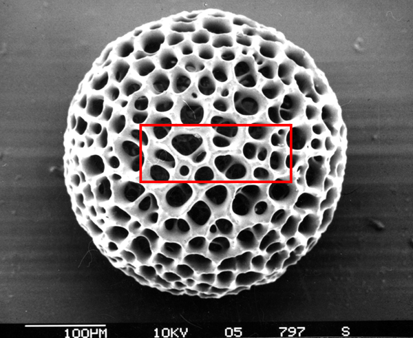
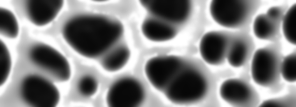
Cropped and Zoomed-In on Image

Gaussian Blur and Highlight Sampling (blur added to reduce noise in original image)
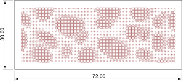
Grasshopper Approximation of Milling Pattern (automatically generates Shop Bot g-code in real-time)
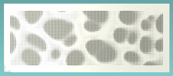
CAD/CAM Preview of Tool Path from Shop Bot Controller (simulation of final cut)
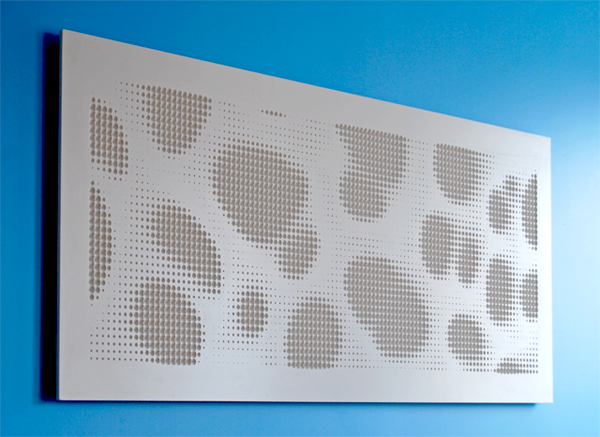
The Final Installed Piece (72"x30"x1/2")
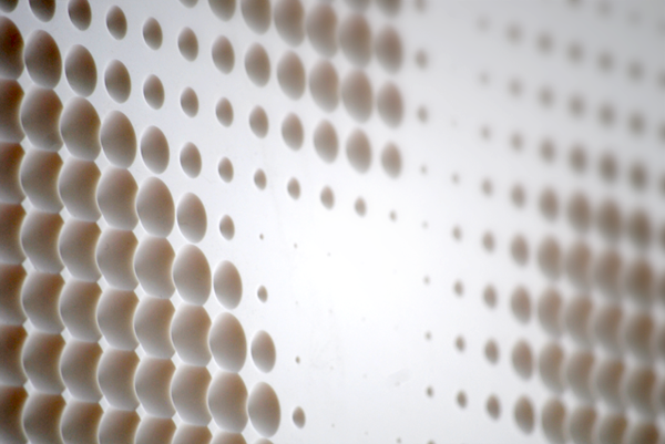
The image becomes more pronounced on the oblique.
The parametric process for this project was relatively straight forward. There have been many examples of patterns generated using the Image Sampler component, and this one is pretty similar to those, so I won’t go into great detail about how that part is set up. The Shop Bot Part file format (.sbp) is essentially just a text file with commands about how the machine should behave. The trickiest part on this entire project was learning the exact command prefixes that are needed to drive the machine. Since these are proprietary (for the Shop Bot), the commands are slightly different than traditional g-code. I found two helpful manuals on the Shop Bot website.
- Command Reference V3 - How to use individual commands in the Control Software
- Programming Handbook - How to program part files
With these two manuals as my guide, it was quite easy to setup the entire tool path part file. I found that the Weave component became very handy when joining together the movements needed for the plunges. I did have to write a little custom code to deal with the header file. This header works for this specific application (using a V-bit 0.75" dia.) but might need some minor modifications if the method of milling were to change (such as surface milling, or profile cutting as opposed to direct plunging). Below are a few screen captures of the Grasshopper definitions.
 Click to Enlarge
The file is meant to be used for academic, and other non-profit institutions for non-commercial, non-profit internal research purposes. This file was created (and tested) in Grasshopper version (0.7.0055). Results may vary if using a different version.
- Grasshopper Shop Bot Writer (369kb - right click and 'Save Link As')
Disclaimer: This file is provided by Andrew Payne | Lift Architects and is furnished "as is". Any express or implied warranties, including, but not limited to, the implied warranties of merchantability and fitness for a particular purpose are disclaimed. In no event shall Andrew Payne be liable for any direct, indirect, incidental, special, exemplary, or consequential damages (including, but not limited to, procurement of substitute goods or services; loss of use, data, or profits; or business interruption) however caused and on any theory of liability, whether in contract, strict liability, or tort (including negligence or otherwise) arising in any way out of the use of this file, even if advised of the possibility of such damage.
Cantilever Bookshelf
 4 Comments


This is a remake of a cantilevered bookshelf I made few years ago. The concept is the same as the previous version, however I've simplified the design and eliminated any kind of connection pieces between the counter weight and the steel plate. Essentially, this bookshelf can be made with one precast concrete counter weight, one structural steel channel, and one custom piece of sheet steel slotted down the middle to accomodate and adjustable bookend (not shown) to stop the books from toppling over as they are placed farther down the shelf.
Wine Bottle Wall
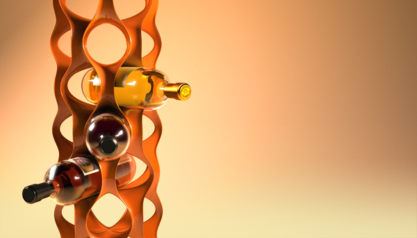
Here is a model I've been working on to develop a wall system that could be digitally fabricated and used to store wine bottles in a unique way. The module, seen on the right, was develped using the Sculpture Generator 1 by Carlos H. Sequin, at UC Berkeley. The modules could be stacked and repeated to form a series of wine rack columns, or duplicated to form a unique wall system.
Cantilever Table
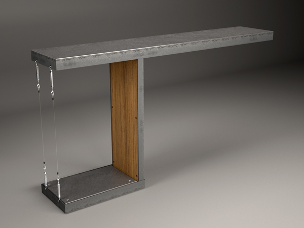
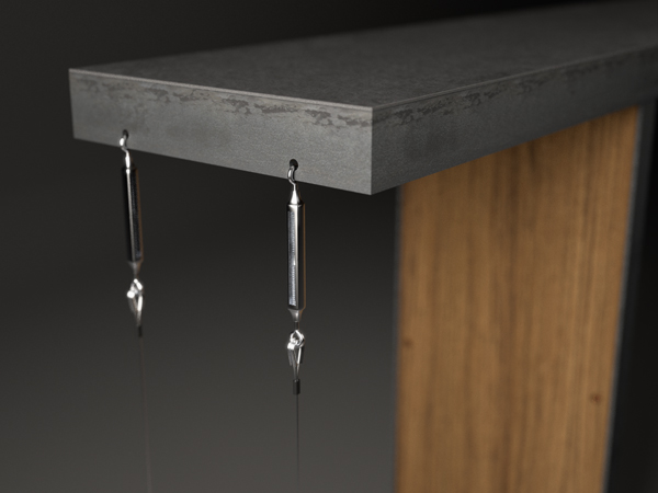
This is a detail of a table that I am creating for a welding class at Cell Space. The concept was to emphasize the cantilever by creating a table with only one leg and thin stainless steel tension wires. The table can support up to 50 lbs of pressure on the far end of the table without overturning and is designed to be assembled in smaller parts instead of one welded piece.
Forces Exploded
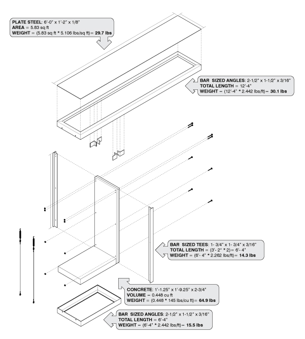
This was the initial force diagram that I created while designing my Cantilever Table, in order to figure out how much weight I needed to counter balance the material weight of the table and the weght of the live loads. My original design called for a pre-cast concrete block to serve as the counter weight (which I did cast, but didn't use) but after solving the forces, I realized that I would need to use 1/4" steel plates instead becuase they were heavier. The overall table weighs about 250 lbs, which I have to agree is a little rediculous, but each piece is made to be bolt connected so that it can be taken apart in smaller assemblages.