![[LIFT] architects](/storage/layout/Header_025.png)
Entries in Research (23)
New Publications
 AOP
in AD, Interactive, News, Research, publications
|
AOP
in AD, Interactive, News, Research, publications
|
 Post a Comment
|
Post a Comment
|
 1 Reference
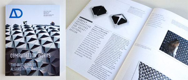
If you haven't already done so, make sure to check out this months issue (April 2013) of Architectural Design (AD) titled Computation Works: The Building of Algorithmic Thought. Edited by Xavier De Kestelier and Brady Peters, this issue focuses on emerging themes in computational design practices, showcasing built and soon-to-be-built projects and providing a state of the art in computational design.
In addition to some amazing articles written by Daniel Davis, David Rutten, Daniel Piker, Giulio Piacentino, Arthur van der Harten, Thomas Grabner and Ursula Frick, and many more... it also features an article that I co-authored with Jason K. Johnson titled Firefly: Interactive Prototypes for Architectural Design. Make sure to check it out, as it's definitely worth the read!
In addition, make sure you also take a look at the book Prototype! edited by Julian Adenauer and Jorg Petruschat which was published by Form+Zweck last summer (2012). Written by leading individuals at world renown design labs and research centers, this book offers a unique compilation of articles centered around the topic of advanced forms of prototyping. In my article, IDE vs. IPE: Toward and Interactive Prototyping Environment I discuss the need to shift toward a more visually oriented Interactive Prototyping Environment (IPE) which addresses the limitations found in the existing IDE paradigm and opens up creative new opportunties for artists and designers.

Printing Material Distributions
AOP
in 3D Printing, Architecture, Objet, Research
|
Post a Comment
|
1 Reference
written by: Panagiotis Michalatos and Andrew Payne
Most digital design involves surface modeling. Even so called “solid” modeling software is based on representations where a “solid” is that which is enclosed by a set of boundaries (known as boundary representations or ‘Brep’ for short). While digital representations of solid objects are often treated as homogeneous and discrete entities, the reality is somewhat different. In the real world, material distributions are continuous and varied. Yet, with regard to architectural components, the variability of material within a volume is usually concealed (ie. porosity of bricks, various types of reinforcements for concrete structures, etc.) and is rarely taken into account during the early design process. With the advent of 3d printing techniques, a new possibility emerges - allowing us the ability to reconsider the aesthetic and mechanical properties of visible reinforcement. In this post we discuss a structural optimization method in conjunction with the possibility of treating structural elements as living in a material continuum that renders objects and reinforcements fuzzy.
Topology optimization is a form finding technique which seeks to optimize a certain material distribution with given boundary conditions (ie. types of supports and loads). It departs from standard form finding techniques in that it assumes that a volume of virtual material can continuously vary its stiffness or density throughout space. Until now the final step of this process involved a cut off threshold; a sharp boundary of hard solid material and void. However intermediate steps of topology optimization suggest grey zones of intermediate material stiffness. These results were usually discarded as unrealistic from a fabrication point of view. With multi material printing we can experiment and speculate about possible realizations of such fuzzy structural objects. The analysis and design of the experiments presented here were carried out using the tools Topostruct (a standalone application) and Millipede (a plugin for Grasshopper) created by Panagiotis Michalatos and Sawako Kaijima.
Three experiments were conducted: the first is the design of a chair using standard topology optimization techniques and interpretation (single solid material), the second was a new type of truss/beam element with fuzzy visible reinforcement (soft transparent material encasing gradations of a harder bone-like structure), and the last one was a similar interpretation to the cantilevering slab which produces patterns reminiscent of a leaf (since leaves solve the same structural problem).
Example 1: A chair
The chair example uses topology optimization to gradually remove material from a solid volume on which the actions of a person seating are applied (ie. vertical and horizontal loads for the seating position). 3d printing allows us the ability to materialize the intricate structures that emerge especially around moment connections.
;)
Figure 1: from left to right: Initial boundary volume setup for chair configuration and successive steps of material redistribution through topology optimization. Darker areas designate denser material.
;)
Figure 2: Features of the chair become more refined during each subsequent step through the topology optimization process.
;)
;)
Figures 3 & 4: Converged geometry of the topology optimization process.
Example 2: A fuzzy truss
For the second experiment we revisited one of the simplest forms from engineering textbooks. The truss like structures that act like bridges supporting a distributed load at their two end points. However, in this example, the topology optimization routine was set up in such a way that instead of a solid object, it yielded a continuous variation of material stiffness. Using Objet’s multi-material printing technology, we were able to develop a gradated structure using a transparent rubbery material and a hard white material (and the gradations in between the two) to achieve an outcome that looks, feels, and structurally acts like a fuzzy reinforced structure.
;)
Figure 5: [top left]: Setup of boundary conditions for simple bridge [main volume + supports at the two lower corners and distributed load at the top]. [top right]: Deflected shape of solid material after load application. [bottom images]: stress distribution and topology optimization contours. Inner contours represent regions where stronger material is required.
;)
Figure 6: Topology optimization drives material redistribution within the volume of the truss. A fuzzy truss shaped beam reinforcement gradually emerges.
;)
Figure 7: A 3d printed diagram showing the distributed load on top and the two supports on either end plus the optimal shape of the reinforced region.
;)
Figure 8: Using multi-material printing technology, a fuzzy bone-like structure can be created using gradients between a transparent rubbery material and an opaque hard material. In this way the actual outcome of the topology optimization process can be directly materialized.
Example 3: A leaf-slab
Our final experiment involved the reinterpretation of a different traditional system - the cantilevering slab. The distributed load over this horizontal plate puts similar requirement to that of a leaf and topology optimization yields branching structures reminiscent of the venation found in leaves.
;)
Figure 9: A fuzzy branching pattern emerges when a distributed load is applied to a cantilevering slab from a single support, resembling the vein patterns of leaves.
;)
Figure 10: A 3d printed diagram showing the cantilevered load and support structure.
;)
Figure 11: Multi-material printing allows us to materialize semi-rigid and semi-transparent fuzzy structural systems as a kind of gradual reinforcement embedded in the material where the boundaries between softer and harder parts are blurred.
The ability to continuously vary the stiffness and transparency of material will allow us to rethink design techniques and technologies, software tools, and analysis methods beyond the surface modeling paradigm. In the scale of product design this is already possible thanks to technologies like multi-material 3d printing. Such experiments will be valuable precedents when speculating about new types of continuous and fuzzy building systems.
This research was generously supported by Objet Technologies. For more information about their 3d printing technology, visit http://www.objet.com.
Firefly + Kinect
Like many people, I've been anxiously awaiting the official release of the Microsoft SDK for the Kinect. Now, that its officially out, I spent some time over the last two weeks working on a set of Kinect related components that I hope to include in the next release of Firefly (1.007). The first component I tried to implement was the Skeleton Tracker... and I have to admit that the result are quite promising. It's surprisingly fast and as long as you stay within the specified range of the sensor, the results are quite good. Using this component I put together two very quick demo videos.
There has been a big push over the last decade to develop novel 3D technology for multimedia displays (whether its new ways for stereoscopic projection, refractive lens, etc.) One of the most successful implementations and inventive (in my opinion) was Johnny Chung Lee's reverse engineering of the Wii sensor bar. Another recent example (and equally impressive) is this hack using the Kinect sensor and head tracking.
The video above is my first attempt to create a real-time 3D display system within Grasshopper using Firefly's new Skeleton Tracker component and some simple camera manipulation. The Skeleton Tracker component outputs a list of points (click here for further explanation). From there, I simply use the Horster Camera Control component (another 3rd party plugin for Grasshopper) to position the camera at the viewers head and the camera target at a point in space locating the Kinect sensor. It really is that easy. Turn on some real-time shadows and you've got a real-time 3D display. It still needs some tweaking but it's pretty fun to play with.
This next demo shows how easy it is to turn gestural movements into physical actuation using an Arduino. The setup is very simple. My z-value of my right hand (basically the height of my hand) controls the brightness value (or Pulse Width Modulation - PWM) of the LED. My left hand controls the servo. When my hand is by my side, the servo goes to position 0 and if I raise my hand above my head the servo moves to position 180. So simple. Of course, this could be expanded to control all sorts of things... perhaps that is next.
Firefly 1.006 New Features
I was extremely excited to announce the official release of Firefly version 1.006 earlier this week. For those who aren't familiar with Firefly, allow me to provide a short introduction. Firefly is a set of software tools dedicated to bridging the gap between Grasshopper (a free plug-in for Rhino), the Arduino micro-controller, the internet and beyond. It allows real-time data flow between the digital and physical worlds and will read/write data to/from internet feeds, remote sensors and actuators, mobile phone devices, the Kinect, and more. There are a lot of new components in this release (including the Arduino Code Generator, Upload to I/O Board, UDP and OSC Listeners and Transmitters, XML Search, and State Detection) that I thought it would be a good idea to put together a few videos showing some of the latest features. So without further ado...
This first video shows the potential of the new Arduino Code Generator and the Upload to I/O Board components. In my opinion, one of the greatest limitations of the previous versions of Firefly was that your Arduino board always had to be tethered to your computer via the USB cable. This was because Firefly communicates back and forth to Grasshopper through serial communication. However, sometimes you just want to use Grasshopper (and its visual programming interface) to prototype your design and then unplug it from your computer to run off external power. Now, you can!
The Arduino Code Generator attempts to convert any Grasshopper definition into Arduino compatible code (C++) on the fly. It works by detecting components that are 'upstream' from the Uno/Mega Write component. The Code Generator checks the component ID against a library of custom C++ functions which then get added to the code if there is a match. The code can be simultaneously saved as a .pde (Arduino Sketch) file to be opened in the Arduino IDE.
In addition, there is also a new Upload to I/O Board component which allows you to upload any sketch (could be from the Code Generator or any other sketch) directly to your Arduino board from within the Grasshopper environment. A lot of stuff happens behind the scenes with this component. Essentially it creates a dynamic MakeFile and calls a shell application to convert the .pde file into a .cpp (C++) file and then into .hex code (machine readable code) to be uploaded to the microcontroller. Note: WinAVR is required to be installed on your machine in order to properly upload sketches to your board. You can download the latest version here.
There are also a lot of great network tools included in this release, including the UDP and OSC Listener and Transmitter components. OSC (Open Sound Control) messages are essentially specially formatted UDP messages which can be particularly handy when you want to send some sort of information across a network (either wirelessly or LAN). OSC messages are particularly useful because each message contains some metadata and a value, giving you more information about what type of data the message contains. These new components open up a whole new world of possibilities by allowing you to send/receive data from smart phones (iphone or android) or by sharing documents among friends or colleagues over a network.
The video above uses the BreathOSC application (free from the iphone app store) developed by Thomas Edwards to simulate wind effects in Grasshopper. Simply breathe into the microphone and an OSC message is sent to a specified IP address on a UDP port. I then simply use the OSC Listener to decode the message and uses its value to create a wind vector to drive the Kangaroo (another 3rd party plugin for Grasshopper) wind simulation. Daniel Piker, the developer of Kangaroo, helped setup this demo... and I have to say... it's quite fun.
Another useful networking application for smart phones is TouchOSC (available for both iphone and android). It supports sending and receiving Open Sound Control messages over a Wi-Fi network using the UDP protocol. You can also create your own interfaces using the TouchOSC Editor and sync them directly to your phone. In this example, I've created a simple layout to control a few LED's, a tri-color LED, and a standard servo using the new OSC Listener in Firefly. This is just a simple test, but the sky is the limit with this type of control over mobile phone interface design.
If you are interested in learning more about Firefly, check out our website at: http://www.fireflyexperiments.com/
The website has a lot of good tutorials and examples to get you up and running in no time. As always, if you have a suggestion or want to send us a comment, you can reach us at info@fireflyexperiments.com
Acknowledgements:
It is without a doubt that this release would not have been possible without the tremendous support from Prof. Panagiotis Michalatos at Harvard's GSD. His guidance over the last 6 months strongly influenced the development of the Firefly_X toolset and I owe him a great debt of gratitude for his assistance. Firefly is built upon the Grasshopper plug-in for Rhino, both developed by Robert McNeel and Associates. The Arduino language syntax is based on Wiring by Hernando Barragan. The Arduino environment is based on Processing byBen Fry and Casey Reas, and is now supported by an amazing team of software and hardware developers that continue to refine and expand its capabilities.
Surface Patterns With The ShopBot Writer for Grasshopper
AOP
in CNC, Corian, Fabrication, Furniture, Research, ShopBot
|
Comments Off
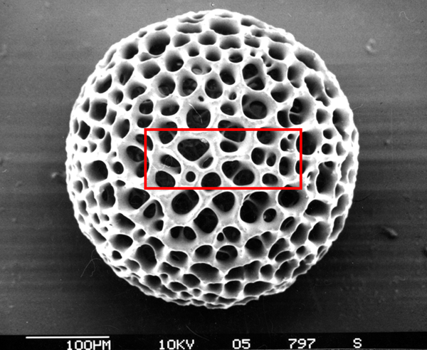
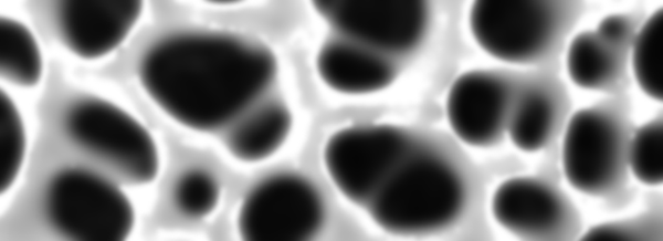
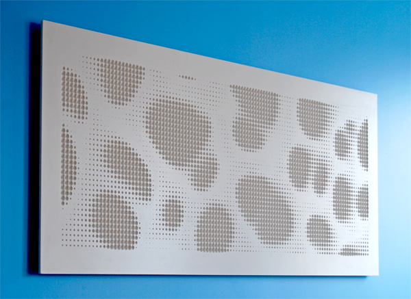
It has been entirely too long since I last posted but that should change over the coming weeks as I've been working on some really amazing projects. To kick things off, I thought I'd share a one week project that I developed to create a dimple halftone pattern on a surface using a custom build Grasshopper definition which writes the all of the G-code (for a ShopBot CNC mill) in real-time. I'll talk more about the fabrication setup below, but first... a little about the concept. I've always been fascinated with the skeletal patterns of Radiolarians (a family of microscopic protozoa that float along the ocean floor). Here's a Wikipedia link for more information. These creatures (perhaps "fossil" is a better word) were made popular by some amazingly detailed and beautiful drawings made by German biologist Ernst Haekel.
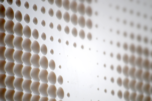
I decided to take something very big (the final piece is milled out of a half size sheet (72"x30") of Corian) out of something that is very very small. To get the desired relief pattern, I used a 3/4" V-bit endmill on the CNC mill so that the circle diameter had a linear relationship to the depth of the plunge. Below are some process images showing the original source image and the step needed to take it into final fabrication using the ShopBot Writer definition I developed for this project.
Before I get to far, there are a few precedent projects that I would like to acknowledge. The 'dimple halftone' pattern idea was a concept developed by Associated Fabrication and 4-pli and was published in Transmaterial 2. MachineHistories has also made a series of beautiful panels that can be seen here. The concept for the work below is inspired by these precedent projects, but the method through which it was employed is new and documented below.
Cropped and Zoomed-In on Image

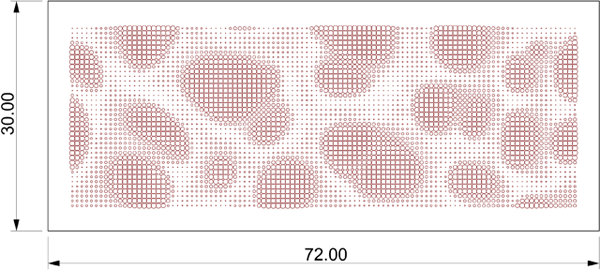
Gaussian Blur and Highlight Sampling (blur added to reduce noise in original image)
Grasshopper Approximation of Milling Pattern (automatically generates Shop Bot g-code in real-time)
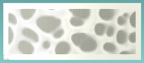
CAD/CAM Preview of Tool Path from Shop Bot Controller (simulation of final cut)
The Final Installed Piece (72"x30"x1/2")
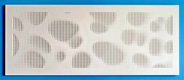
The image becomes more pronounced on the oblique.
The parametric process for this project was relatively straight forward. There have been many examples of patterns generated using the Image Sampler component, and this one is pretty similar to those, so I won’t go into great detail about how that part is set up. The Shop Bot Part file format (.sbp) is essentially just a text file with commands about how the machine should behave. The trickiest part on this entire project was learning the exact command prefixes that are needed to drive the machine. Since these are proprietary (for the Shop Bot), the commands are slightly different than traditional g-code. I found two helpful manuals on the Shop Bot website.
- Command Reference V3 - How to use individual commands in the Control Software
- Programming Handbook - How to program part files
With these two manuals as my guide, it was quite easy to setup the entire tool path part file. I found that the Weave component became very handy when joining together the movements needed for the plunges. I did have to write a little custom code to deal with the header file. This header works for this specific application (using a V-bit 0.75" dia.) but might need some minor modifications if the method of milling were to change (such as surface milling, or profile cutting as opposed to direct plunging). Below are a few screen captures of the Grasshopper definitions.
 Click to Enlarge
The file is meant to be used for academic, and other non-profit institutions for non-commercial, non-profit internal research purposes. This file was created (and tested) in Grasshopper version (0.7.0055). Results may vary if using a different version.
- Grasshopper Shop Bot Writer (369kb - right click and 'Save Link As')
Disclaimer: This file is provided by Andrew Payne | Lift Architects and is furnished "as is". Any express or implied warranties, including, but not limited to, the implied warranties of merchantability and fitness for a particular purpose are disclaimed. In no event shall Andrew Payne be liable for any direct, indirect, incidental, special, exemplary, or consequential damages (including, but not limited to, procurement of substitute goods or services; loss of use, data, or profits; or business interruption) however caused and on any theory of liability, whether in contract, strict liability, or tort (including negligence or otherwise) arising in any way out of the use of this file, even if advised of the possibility of such damage.
Using Grasshopper to Control a Pan/Tilt Servo
The above is a follow up video to the posting I made last week showing how we can use a Wii nunchuck to control parametric data in Grasshopper. However, in this video, we are looking at reversing the flow of information and using parametric data (numeric sliders in Grasshopper) to control two different servos. In this case, one slider controls the panning servo, while the other controls the tilting servo.
In this demo, we need to set up two different files. The first is the Grasshopper definition (written for ver. 0.6.0019) which sends the numeric slider information over the serial port via a custom VB.NET component. This component formats the two variables (the pan slider and the tilt slider) into a string that is separated by a comma. This comma will serve as our delimeter when we read the data over the serial port on the Arduino side. You can download the Grasshopper source file below.
On the Arduino side, we first have to understand that serial communication receives individual bytes of information as a stream. This can become complicated because most data types are more than 1 byte... so you have to understand the data type and then convert it on the Arduino side to the format you are looking for. In this example, we are reading a string into the buffer and then working through each individual byte until we reach our delimeter (don't forget about the comma). Once we reach the comma, we pass the data that has been read into the buffer into a variable that ultimately controls one of the servos. We do a similar process for the second set of bytes after the comma. The Arduino source code can also be downloaded below.
Again, I'd like to thank Robert Lee for his explanations and insights on how to set up this demo.
Source Files:
Grasshopper_controlling_PanTilt_Servo.pde (Right-click to 'Save Link As') This is the Arduino source code needed to program the micro-controller. This file was written for Arduino IDE ver. 0017.
Grasshopper to PanTilt Servo.3dm (Right-click to 'Save Link As') This is the Rhino file that accompanies the Grasshopper definition.
Update: Please use the new FireFly toolbar to facilitate the Grasshopper to Arduino connection. Click here for more information.
Note: These documents are in the public domain and are furnished "as is". The author, Andrew Payne, makes no warranty, expressed or implied, as to the usefulness of the software and documentation for any purpose. This work is licensed under a Creative Commons Attribution-Share Alike 3.0 United States License. http://creativecommons.org/licenses/by-sa/3.0/us/
Using a Wii Nunchuck to Control Grasshopper
The video above demonstrates how we can feed a stream of live sensor data (in this case, I chose to use the accelerometer data from a Wii nunchuck) into Grasshopper to control a parametric model. I'll be the first to admit that this is not a 'new' demo... In fact, this demo was heavily inspired (in concept) by this video that was created in 2008 that shows how a Wii nunchuck can control a mechanical arm in 3D Studio Max .
However, my own research was primarily concerned with understanding how to get the sensor data into Grasshopper (and how we can also reverse this flow of information to get Grasshopper to control servos, motors, LED's, etc...) in order to create more complex and sophisticated digitial and physical environments.
Before we get too far, I'd like to say thank you to Robert Lee for his insights on how to setup the VB.NET listener.
Now onto the more technical aspects. Let's start with the hardware setup. I am sending the accelerometer data from the Wii nunchuck to an Arduino Diecimila micro-controller which allows me to format the data into a block of code that the Grasshopper VB.NET listener will be able to understand. I could have spliced up my Wii controller to connect the various parts of the circuit to the appropriate pins on the Arduino board, but I decided to buy a wonderful and cheap little adapter that simplifies the entire process. You can buy your own from these online stores:
- FunGizmos.com. International shipping for $1 more.
- Tinker.it (UK)
- Little Bird Electronics (Australia)
- Sparkfun. Ships domestic & internationally. Be sure to order header pins too!
- Freduino.eu (EU)
Now, that we've properly connected the Wii nunchuck to our micro-controller, we'll need to program our Arduino board so that it can read the incoming sensor data and send it over the serial port. For this, I have used a custom built library written by Tod E. Kurt that was designed to help the communication process between a Wii controller and the Arduino. You can download the "nunchuck_funcs.h" library from his website at: http://todbot.com/blog/. You can also get the source file needed to program your own board by clicking on the links below.
On the Grasshopper side of things, we need to create a custom VB.NET listener component that can read a string of data coming in over the serial port. The nice thing about this listener is that it will display any string that is being sent from the Arduino... What you do with that string is another matter... but in this example, we are feeding a string of information that is separated by a comma ",". The comma will be our delimeter which essentially tells us where to split the string so we can extract the integer value on the left side of the comma (which cooresponds to the X-value of the accelerometer) and the integer value on the right side of the comma (which will cooresponds to the Y-value of the accelerometer).
Once we have successfully read the data from Grasshopper, we can connect a Timer Component to automatically refresh the solution at a given time interval. In the video above, I was able to refresh the sensor data at 50 millisecond (the smallest time interval that is currently available in Grasshopper) without any lag or delay. You can download both the Rhino file and the Grasshopper definition needed for this demo by clicking on the links below.
Source Files:
Wii Nunchuck to Grasshopper.pde (Right-click to 'Save Link As') This is the Arduino source file. This file was written for Arduino IDE ver. 0017.
Wii Nunchuck to Grasshopper.3dm (Right-click to 'Save Link As') This is the Rhino file that accompanies the Grasshopper definition.
Update: Please use the new FireFly toolbar to facilitate the Grasshopper to Arduino connection. Click here for more information.
Note: These documents are in the public domain and are furnished "as is". The author, Andrew Payne, makes no warranty, expressed or implied, as to the usefulness of the software and documentation for any purpose. This work is licensed under a Creative Commons Attribution-Share Alike 3.0 United States License. http://creativecommons.org/licenses/by-sa/3.0/us/
Testing the Grasshopper G-code Writer for 2D Shape Milling
This video shows some on going research on how the Grasshopper plugin for Rhino can streamline the CNC milling fabrication process; specifically for 2D shape milling on a PADE spin-W 5 axis continuous CNC Work Center. Special thanks to Matthew Spremulli (former University of Toronto Grashopper workshop attendee) and Greg Everett of the Airport Railings & Stairs Co. Ltd. located in Mississauga Ontario Canada for running the code on their 5-axis CNC mill.
The original Grasshopper definition has been updated to write both the G-codes (which are the individual groups of numerically controlled functions called packets which tell the mill how and where to move) and the P-codes (which are the instructions that are read by the PADEeasy software to call up the packets in a specific order). Both sets of codes are streamed automatically to .txt files and are automatically updated upon any changes in the definition or Rhino geometery.
More videos to come on surface milling and 5-axis milling techniques.
Team:
Parametric Modeling - Andrew Payne & Matthew Spremulli
CNC Milling - Greg Everett
Fabrication Tools:
Parametric Modeling Software - Grasshopper plugin for Rhino
CAM Manager - PADEeasy
CAM Controller - OSAI Controller
CNC Milling Machine - PADE spin-W 5 axis continuous CNC Work Center
Fabrication Shop:
Airport Railings & Stairs Co. Ltd. located in Mississauga Ontario Canada
Grasshopper G-Code Writer for Surface Milling
In this video, we will walk through how to setup a Grasshopper definition that will write the G-code for surface milling on a 3-axis CNC milling machine. When surface milling - the contouring engine is crucial. For speed reasons, I found the C# contouring definition written by Giulio Piacentino works extremely well because it allows the user to specify a step distance (tool path offset). After we have generated the contours (or tool paths) we can subdivide each curve, using the evaluate length component, to create a series of points which will guide the CNC mill head in order. Because we now have data structures, we can weave formatted text strings that have been derived from the point data into a G-code that will work with the ShopBot CAM software.
As in the previous example, we have formatted our text strings to work with the opensource CAM software, Shopbot. You can download a free version of the software here: http://www.shopbottools.com/controlsoftware.htm.
You can also check out this video in HD after the jump.
Note: This video is for demonstration purposes only. Andrew Payne and LIFT architects will not be held responsible for any damages that might arise from using this method. Please consult your machine's operating manual before implementing this fabrication method.
Grasshopper G-Code Writer for 2D Shape Milling
In this video, I will explain how to setup a Grasshopper definition that will write the G-code for 2D shape milling on a 3-axis milling machine. G-codes are the codes that position the tool and do the actual work, as opposed to M-codes which manages the machine. Actually, there are a whole host of different codes that can be written to control a CNC mill, however G-codes are what we are most interested in for this definition as it will allow us to streamline our fabrication process by sending the parametric data from Grasshopper directly to a CNC mill.
In this example I will be writing the tool path information for a 2D Vornoi Pattern generator, originally written by Sang Hoon Yoon. You can find his vornoi diagram definition on his site www.sac3.blogspot.com. This video explains how to use your data-structure (trees) to help weave together various text strings which control how the CNC mill head will operate.
I have formated the text strings to work with the open source ShopBot CAM software. This software is excellent for many reason, not least of which is the fact that it's free and has a large online help community... much like Grasshopper. It also allows the user to preview the cut even if their computer isn't connected to an actual CNC mill which can come in handy while testing out your cuts. Syntactically, ShopBot part files are setup slightly differently from traditional G-code which harkens back to the days when cutting files were stored on punched tape and it's format was optimized for brevity. You can find a lot of helpful resources on how to setup ShopBot part files in their Programming Handbook.
You can check out this video in HD after the jump.
Note: This video is for demonstration purposes only. Andrew Payne and LIFT architects will not be held responsible for any damages that might arise from using this method. Please consult your machine's operating manual before implementing this fabrication method.
Waffle Structural System: Using Grasshopper to Output Structural Ribs to a Laser Cutter or CNC Mill
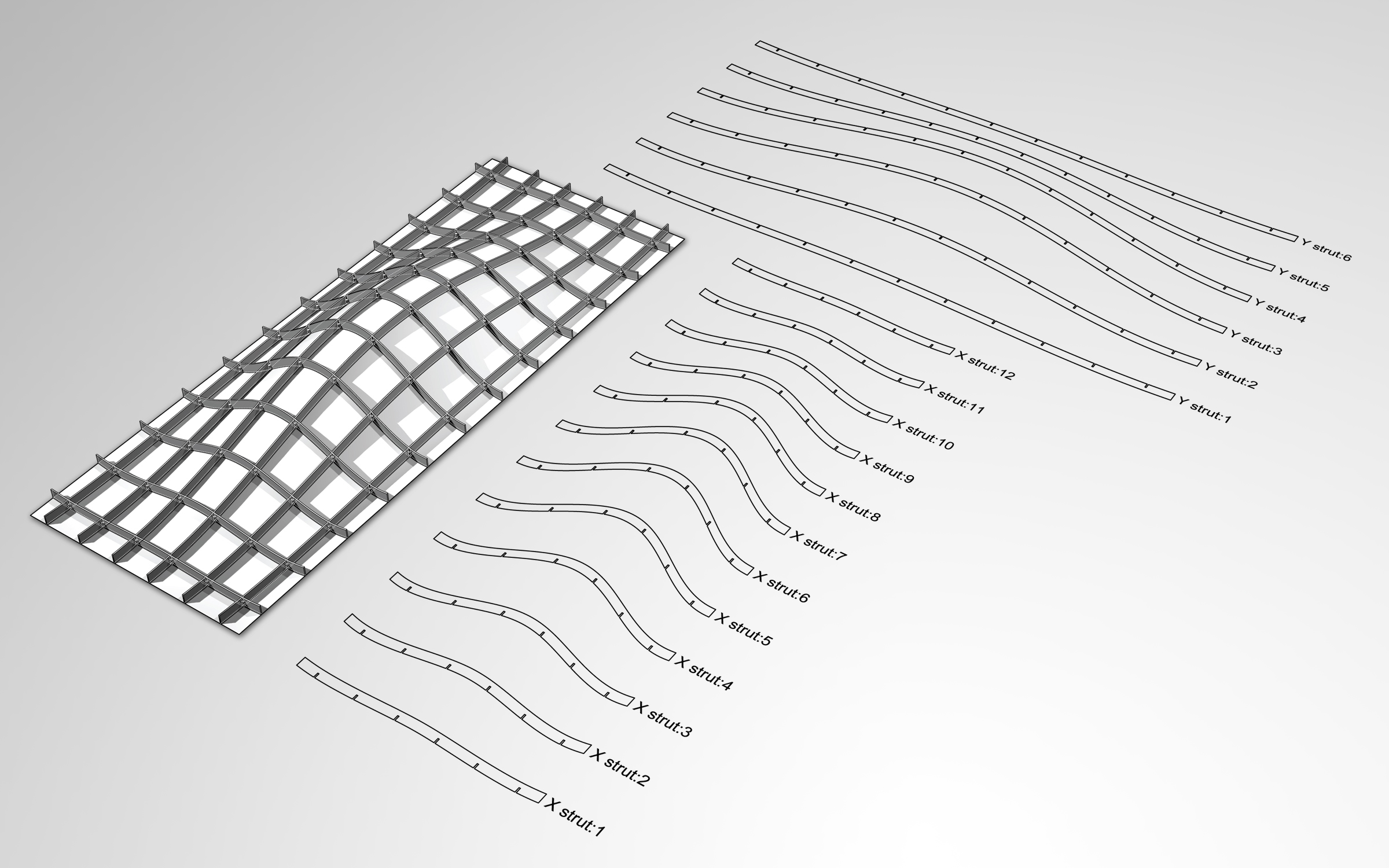 Click to see larger imageI have been working on a definition for Rhino's Grasshopper plugin that would create a notched "waffle" structural system for any given surface. With this definition, you can specify the number of struts in the X & Y axis as well as the strut depth and the notch thickness (or the strut material thickness). The waffle system has a few components that define the strut labels and has a slider to control the label size to keep the model organized. Finally, the definition orients the strut curves to the X-Y axis so that the curves can be easily output directly to a CNC mill or laser cutter.
Also, if you are able to use this definition to create a waffle structure of your own (either laser cut or CNC milled), please email me some images and I will post the work on this website. Good luck.
Source File:
Waffle_Structural_System.gh (size: 25k - file updated by GH user msieurju on 11.05.11 to work with Grasshopper v0.8.0052 or higher. I'd like to express my thanks for the udpate.)
Note: This software and its documents are in the public domain and are furnished "as is". The author, Andrew Payne, makes no warranty, expressed or implied, as to the usefulness of the software and documentation for any purpose. This work is licensed under a Creative Commons Attribution-Share Alike 3.0 United States License. http://creativecommons.org/licenses/by-sa/3.0/us/
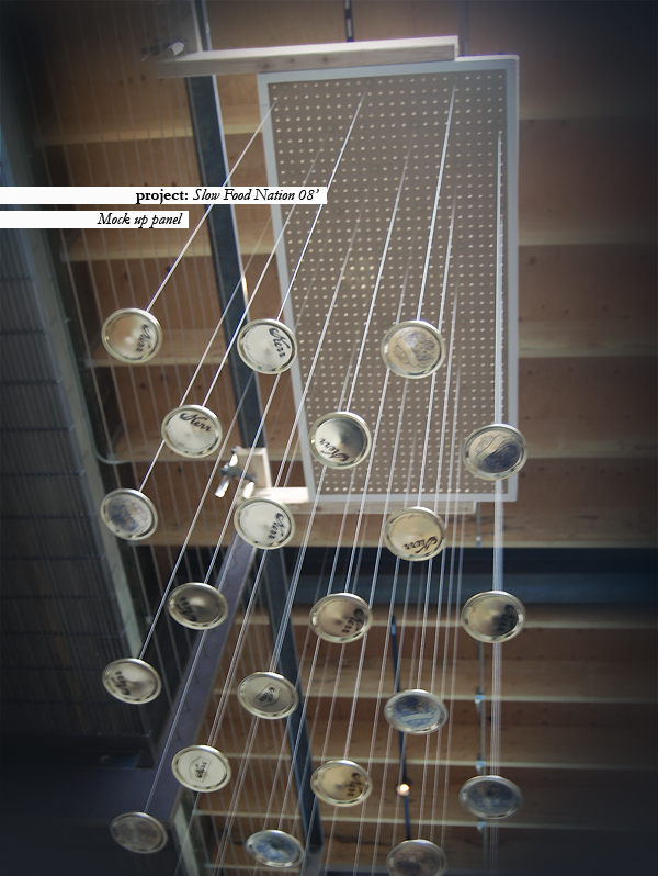
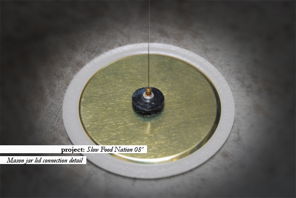
Lid of Lids Mockup
Our team finally decided to go forth with our second full scale mockup of the suspended mason jar ceiling and here are a few shots from this weekend's test. I was pretty satisfied with our connection detail between the mason jar lid and the fishing line that we are using to suspended the lid from the peg board ceiling. We were able to come up with a system that eliminates all knot tying by threading the fishing line through the back of an ear ring and sandwiching it between the ear ring back and the back side of one piece of a circular velcro strip. It did take a little practice, but overall the system seems to work pretty efficiently. The velcro also allows for some adjustability which will hopefully work in our favor once we begin final assembly.