![[LIFT] architects](/storage/layout/Header_025.png)
Entries in Fabrication (2)
A Five-Axis Robotic Motion Controller For Designers
 AOP
in ACADIA, Fabrication, Firefly, Robotics, Writings
|
Comments Off
AOP
in ACADIA, Fabrication, Firefly, Robotics, Writings
|
Comments Off
I'm excited to release more information about a paper I wrote titled A Five Axis Robotic Motion Controller for Designers which was selected for publication and presentation for this year's ACADIA 2011 Conference: Integration Through Computation held in Banff, Canada from October 13th-16th. Click here to download the full paper.
This project aims to bring physical input and output closer together through the design purpose-built tools for fabrication, which hopefully leads to many new creative opportunities for designers. Working from observations about the way architects design, this project explores the development of a novel 3D drawing tool or customized 5-axis digitizing arm that takes real-time input and translates movement patterns directly into machine code for robotic fabrication. An improved workflow for robotic simulation was also developed as part of this project; using design tools that are already familiar to architects and designers, such as Rhino and Grasshopper. The purpose of this project was not to suggest that this new workflow is a ready-made solution to replace the existing robotic fabrication process; rather I hope that this work is seen as a proof of concept that could enable wider use of digital fabrication tools by architects and designers.
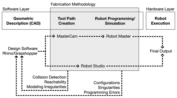
The existing design-to-fabrication workflow for industrial robots (seen above) has traditionally been a slow and cumber-some process, especially for designers. Machine tooling, kinematic simulations, and robotic movement programming often require intimate knowledge of scripting and manufacturing processes, all of which limit the utilization of such tools by the 'typical' architect/designer.
In the traditional robotic fabrication workflow, there is often a discrepancy between the original design intent and the final output, primarily because there is an intermediate step where the designer has to hand off a digital model to a fabrication consultant who has more intimate knowledge of the specific robotic CAM software and the fabrication process in general. Typically, this consultant will use programs such as Robot Studio or Master CAM to create the necessary tool paths for the design, however this process can often take a great deal of time. And, if during this process, modeling irregularities are found or fabrication problems arise due to reachability or collision detection issues, then the entire process must start anew.
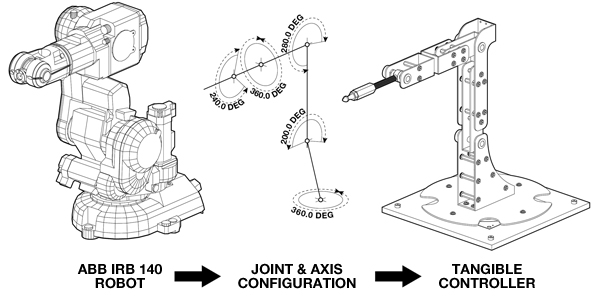
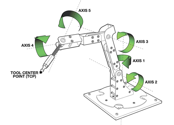
Conceptually, this project started very simply. I began by looking at the joint and axis configurations of the ABB-IRB 140 robot, one of the six axis robots available in the Harvard robotics lab. The design challenge then, was to design a tangible controller around these constraints. By using the same joint and axis configurations, the digitizing arm has a one to one relationship with the larger industrial robot. It is very intuitive. A user immediately grasps the idea that when they move the digitizing arm in a certain way, the robot will respond in kind.
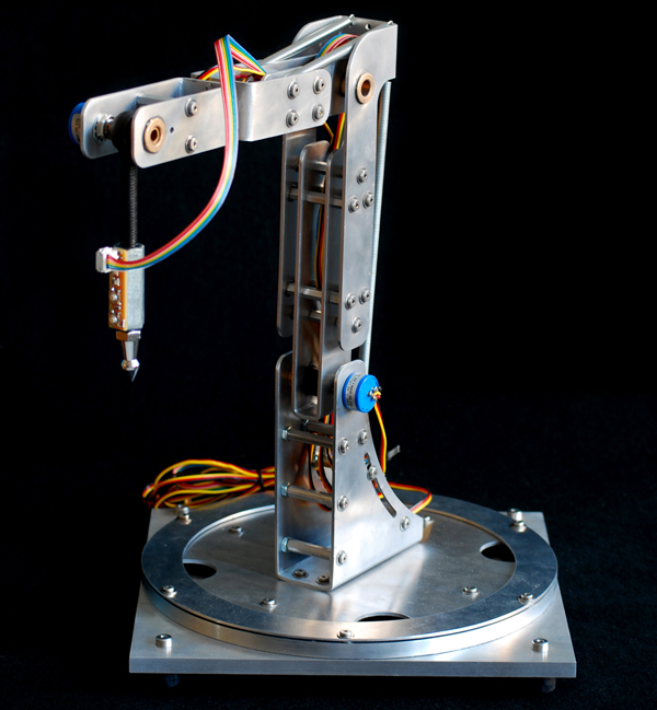
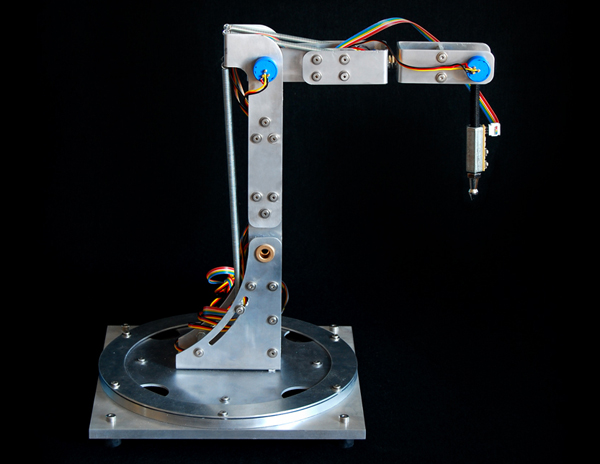
Outside of the development of a new robotic workflow, one of the primary goals of the project was to minimize costs. Given that all of the parts for this project were paid for out of pocket (a student's pocket), creating a low-cost solution was of utmost importance. But, beyond my own personal economic restrictions, I wanted this project to be seen as a do-it-yourself solution - something that could be built in any garage or workbench using easily purchased hardware parts and sensors and a few custom fabricated pieces. The entire controller, shown here, was built for less than $200 dollars. The aluminum body was water jet cut and all of the hardware were pieces that could purchased from local hardware stores or online retailers. All of the sensors, including the five high-precision potentiometers (shown here as the small blue knobs sticking off of the aluminum body) and the two digital sensors on the tool tip were also purchased from online retailers and were chosen because of their affordability.
To create a real-time robotic simulation, data from each of the embedded sensors on the tangible controller are streamed into the computer using a plug-in for Grasshopper that I have also been developing called Firefly. Among other things, Firefly enables the use of real-world data, acquired from various types of sensors or other input devices to explicitly define parametric relationships within a Grasshopper model. In this project, sensor information is used to create a forward kinematic robotic simulation. Forward kinematics describes one type of solution for determining robotic positioning. If given all of the relative angles of each joint and the lengths of each leg; the tool tip (also known as the end effector) can be found by performing a series of matrix transformations on each body in the robotic mechanism. In this case, each of the potentiometers will return a 10-bit number between 0 and 1023. These particular potentiometers were able to rotate up to 340º, so the angle between each joint can be found by simply multiplying the current sensor value by the sensor step size. These angle values are used to perform a matrix transformation on each of the robotic legs, ultimately giving you the precise position of the tool center point. And, once you know the location of the end effector, you can record this data over time to create real-time robotic tool paths.
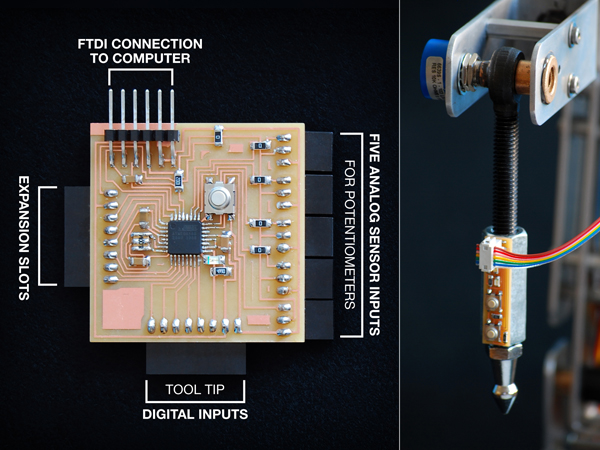
In addition to the five high-precision potentiometers, the digitizing arm is equipped with a tool tip circuit board with two push button controls. These allow the user to easily record or reset the digitized information on the fly. I also designed and built a customized circuit board (on the left) which processes all of the sensor information and sends a formatted string of information over the serial port to the virtual parametric interface.
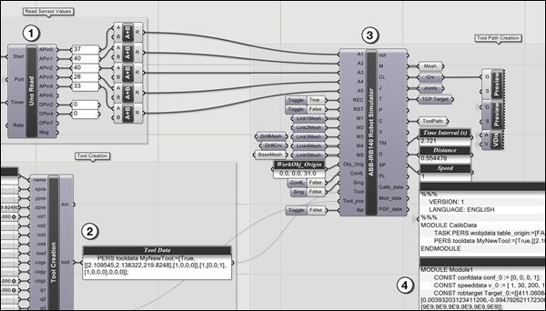
The Grasshopper definition is relatively straight forward. The Firefly Read component parses of the sensor information being sent directly from the microcontroller circuit board. There is a custom component written in VB.NET (seen in item number 2), which creates the necessary tool data. The data from both of these components are fed into another custom component which calculates the forward kinematic solution and outputs the position of each leg, creating a real-time preview of the robot moving in the Rhino viewport. In addition, the robotic simulator also returns all of the RAPID code, or the robotic programming language used by all of the ABB robots, to move the actual robot in the same manner as the forward kinematic preview.
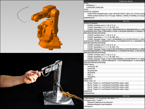
The custom robotic simulation component written inside of Grasshopper outputs all of the necessary RAPID code to control the actual robot. There are two methods by which this can be done. First, all of the digitizing information is recorded and formatted into a composite data type called a robtarget. Each robtarget is defined by its name, absolute position as XYZ coordinates, rotation and orientation of the robot as four quaternion values, and its joint configurations. Each robtarget is given a unique identification each time the solution is recomputed. Then the movement commands are created to tell the robot specifically how to get to each robtarget. Once the program has been written, it can then be saved to a file on disk and uploaded to the robotic controller to be played back. An alternative method is to stream the angle information from the digitizing arm directly to the robot through a network cable. In this method, a program is uploaded to the robot which tells it to sit and wait for any information being sent directly from the Grasshopper definition (which can be seen in the video above).
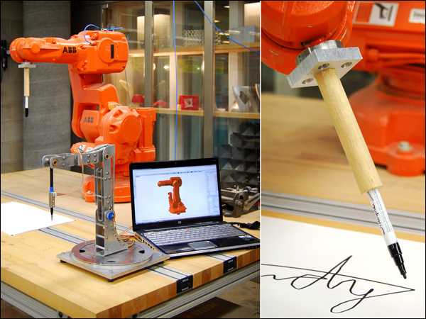
As of today, there have only been a limited number of test runs using the five-axis robotic controller, however, the initial tests suggest that the proposed direct-to-fabrication process could prove to be a viable alternative to existing robotic workflows. One of the first tests I tried was attaching a custom designed pen tool to the robot to see if the drawing movements of the digitizing arm would match those of the robot. And while spelling your name isn't the most exciting demo, it did show some of the potential available with this process. Because virtually any end effector can be attached to the end of the robot, the design opportunities are endless. And because the tangible controller has a one-to-one relationship with the larger industrial robot, designers immediately understand that their drawing motions will be converted directly into robotic movements, creating a very intuitive interface.
Although there has been considerable progress made in the digital tools used to control robots, I'd like to close by reiterating the fact that there is an identifiable problem in the existing design-to-fabrication process. I would like to propose an improved workflow for robotic fabrication. It is the hope of this project that the physical articulation of embodied input and output through purpose-built tools for fabrication can allow for wider adoption by and new creative opportunities for architects and designers. In turn, I hope this will help re-establish the relationship between designers and the physical fabrication process.
Acknowledgments:
I would like to thank Harvard professors Martin Bechthold and Pangiotis Michalotos as well as Neil Gershenfeld from MIT's Center for Bits and Atoms for their support during the development of this project.
Surface Patterns With The ShopBot Writer for Grasshopper
AOP
in CNC, Corian, Fabrication, Furniture, Research, ShopBot
|
Comments Off
It has been entirely too long since I last posted but that should change over the coming weeks as I've been working on some really amazing projects. To kick things off, I thought I'd share a one week project that I developed to create a dimple halftone pattern on a surface using a custom build Grasshopper definition which writes the all of the G-code (for a ShopBot CNC mill) in real-time. I'll talk more about the fabrication setup below, but first... a little about the concept. I've always been fascinated with the skeletal patterns of Radiolarians (a family of microscopic protozoa that float along the ocean floor). Here's a Wikipedia link for more information. These creatures (perhaps "fossil" is a better word) were made popular by some amazingly detailed and beautiful drawings made by German biologist Ernst Haekel.
I decided to take something very big (the final piece is milled out of a half size sheet (72"x30") of Corian) out of something that is very very small. To get the desired relief pattern, I used a 3/4" V-bit endmill on the CNC mill so that the circle diameter had a linear relationship to the depth of the plunge. Below are some process images showing the original source image and the step needed to take it into final fabrication using the ShopBot Writer definition I developed for this project.
Before I get to far, there are a few precedent projects that I would like to acknowledge. The 'dimple halftone' pattern idea was a concept developed by Associated Fabrication and 4-pli and was published in Transmaterial 2. MachineHistories has also made a series of beautiful panels that can be seen here. The concept for the work below is inspired by these precedent projects, but the method through which it was employed is new and documented below.
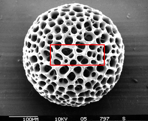
Cropped and Zoomed-In on Image

Gaussian Blur and Highlight Sampling (blur added to reduce noise in original image)

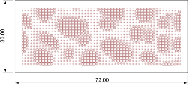
Grasshopper Approximation of Milling Pattern (automatically generates Shop Bot g-code in real-time)
CAD/CAM Preview of Tool Path from Shop Bot Controller (simulation of final cut)
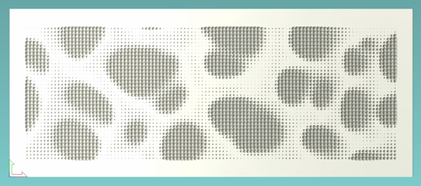
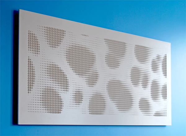
The Final Installed Piece (72"x30"x1/2")
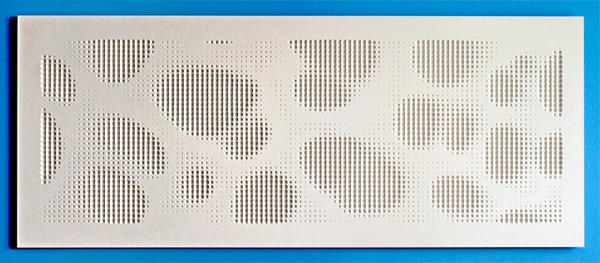
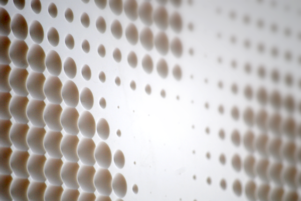
The image becomes more pronounced on the oblique.
The parametric process for this project was relatively straight forward. There have been many examples of patterns generated using the Image Sampler component, and this one is pretty similar to those, so I won’t go into great detail about how that part is set up. The Shop Bot Part file format (.sbp) is essentially just a text file with commands about how the machine should behave. The trickiest part on this entire project was learning the exact command prefixes that are needed to drive the machine. Since these are proprietary (for the Shop Bot), the commands are slightly different than traditional g-code. I found two helpful manuals on the Shop Bot website.
- Command Reference V3 - How to use individual commands in the Control Software
- Programming Handbook - How to program part files
With these two manuals as my guide, it was quite easy to setup the entire tool path part file. I found that the Weave component became very handy when joining together the movements needed for the plunges. I did have to write a little custom code to deal with the header file. This header works for this specific application (using a V-bit 0.75" dia.) but might need some minor modifications if the method of milling were to change (such as surface milling, or profile cutting as opposed to direct plunging). Below are a few screen captures of the Grasshopper definitions.
 Click to Enlarge
The file is meant to be used for academic, and other non-profit institutions for non-commercial, non-profit internal research purposes. This file was created (and tested) in Grasshopper version (0.7.0055). Results may vary if using a different version.
- Grasshopper Shop Bot Writer (369kb - right click and 'Save Link As')
Disclaimer: This file is provided by Andrew Payne | Lift Architects and is furnished "as is". Any express or implied warranties, including, but not limited to, the implied warranties of merchantability and fitness for a particular purpose are disclaimed. In no event shall Andrew Payne be liable for any direct, indirect, incidental, special, exemplary, or consequential damages (including, but not limited to, procurement of substitute goods or services; loss of use, data, or profits; or business interruption) however caused and on any theory of liability, whether in contract, strict liability, or tort (including negligence or otherwise) arising in any way out of the use of this file, even if advised of the possibility of such damage.